Removal and Installation
C235 – Without Air Suspension
▸Contents: 03 - Differential and Driveline
Description and Operation
- Front Axle - 215fd
- Rear Axles - C235 And Rba260
- Rear Axle - M250 (2021 - Present)
Diagnosis and Testing
- Axle Diagnosis
- Driveshaft
- Halfshaft
Standard Procedure
- Drain And Refill
- C235 Drain And Refill
- M250 Drain And Refill
- Rba260 Drain And Refill
Adjustments
- Center Support Bearing Adjustments
- Adjustments - C235
- Adjustments - M250
- Adjustments - Rba260
Technical Specifications
- General Specifications - 215fd
- General Specifications - C235
- General Specifications - M250
- General Specifications - Rba260
- Torque Specifications
Special Tools
- Special Tools - 215fd
- Special Tools - C235
- Special Tools - M250
- Special Tools - Rba260
Removal and Installation
- 215fd - 3.0l Diesel
- 215fd - 3.6l Engine
- 215fd - 5.7l - 6.2l Engine
- C235 – Without Air Suspension
- C235 – With Air Suspension
- C235 – Thermal Rear Axle
- M250
- Rba260 – Without Air Suspension
- Rba260 – With Air Suspension
ASSEMBLY, Differential
Removal and Installation
- Differential Assembly - C235 - Open
- Differential Assembly - C235 - Limited Slip
- Differential Assembly - C235 - Electric Locking
- Differential Assembly - M250
- Differential Assembly - Rba260 - Limited Slip
- Differential Assembly - Rba260 - Electric Locking
Disassembly and Assembly
- C235 - Open Differential
- C235 - Limited Slip Differential
Actuator/Motor
- Removal and InstallationFront Axle Disconnect
Bearings
Removal and Installation
- Axle Shaft Bearing - C235
- Axle Shaft Bearing - M250
- Axle Shaft Bearing - Rba260
- Driveshaft Center Bearing
- Output Shaft Bearing - 215fd
- Differential Side Bearings - C235
- Differential Side Bearings - M250
- Differential Side Bearings - Rba260
Cover
Removal and Installation
- Differential Cover - C235 - Without Thermal Axle
- Differential Cover - C235 - With Thermal Axle
- Differential Cover - M250
- Differential Cover - Rba260
GEAR, Ring and Pinion
Removal and Installation
- Ring And Pinion Gear - C235
- Ring And Pinion Gear - M250
- Ring And Pinion Gear - Rba260
Joints
Removal and Installation
- Removal And Installation - Single Cardan With Injected Ring
- Removal And Installation - Single Cardan With Snap Rings
Seals
Removal and Installation
- Front Axle Seals - 215fd
- Axle Seal - C235
- Axle Seal - Rba260
- Pinion Seal - 215fd
- Pinion Seal - C235
- Pinion Seal - M250
- Pinion Seal - Rba260
SHAFTS, Axle/Drive/Half
Removal and Installation
- Axle Shaft - C235
- Axle Shaft - M250
- Axle Shaft - Rba260
- Front Driveshaft
- Front Halfshaft
- Output Shaft - 215fd
- Rear Driveshaft
Valves
Removal and Installation
- Three-Way Coolant Valve
- Thermal Rear Axle Coolant Lines
REMOVAL
- Disconnect and isolate the negative battery cable. If equipped with an Intelligent Battery Sensor (IBS), disconnect the IBS connector first before disconnecting the negative battery cable.
- Raise and support the vehicle (Refer to 04 - Vehicle Quick Reference/Hoisting - Standard Procedure) .
- Remove both rear wheels (Refer to 22 - Tires and Wheels/Removal and Installation) .
- Disconnect both rear wheel speed sensor wire harness connectors. (Air suspension shown, Coil suspension rear wheel speed sensor wire harness connector location and bracket location identical.)
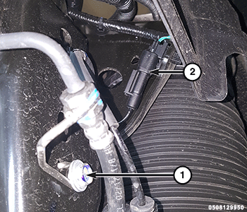
1 – Rear Brake Hose Routing Bracket Bolt 2 – Rear Wheel Speed Sensor Wire Harness Connector - Remove both rear caliper adapters (Refer to 05 - Brakes, Base/Hydraulic/Mechanical/ADAPTER, Disc Brake Caliper/Installation) .
- Loosen the clamp and disconnect the axle vent hose from the axle.
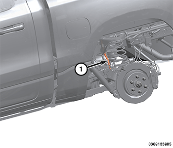
1 – Vent Hose - Remove the rear driveshaft (Refer to 03 - Differential and Driveline/SHAFTS, Axle/Drive/Half/Removal and Installation) .
- Remove and DISCARD the upper control arm bracket bolts and nuts and position the upper control arms aside away from the axle.
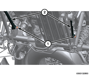
1 – Upper Control Arms 2 – Upper Control Arm Bolts And Nuts At Axle - Remove the stabilizer bar bolts, the stabilizer bar brackets and position aside the stabilizer bar.
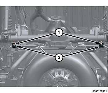
1 – Stabilizer Bar Bolts 2 – Stabilizer Bar Brackets - Position a lift under the axle and secure the axle to the lift.
- Remove and DISCARD the track bar axle bolt.
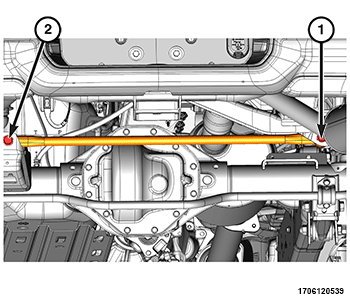
1 – Track Bar Frame Bolt 2 – Track Bar Axle Bolt - Remove both lower shock absorber bolts and nuts and position the shock absorbers away from the axle.
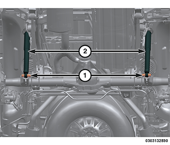
1 – Lower Shock Absorber Bolts And Nuts 2 – Shock Absorber - Remove and DISCARD the lower control arm bolts and nuts and position the lower control arms away from the rear axle.
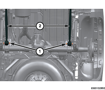
1 – Lower Control Arm Bolts And Nuts 2 – Lower Control Arm - If equipped with coil springs, slightly lower the rear axle assembly and remove the rear coil springs.
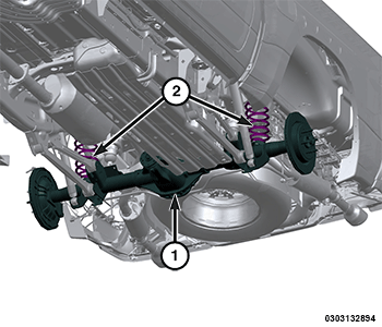
1 – Rear Axle Assembly 2 – Coil Springs - Remove the rear axle from the vehicle.
INSTALLATION
| NOTE: |
All suspension torques should be made with the full vehicle weight on the ground being supported by the tires. |
- Position the coil springs in place on the rear axle and align into the spring upper pocket.
- Carefully raise the rear axle in place.
1 – Rear Axle Assembly 2 – Coil Springs - Position both the lower control arms into the rear axle brackets and loosely install the NEW lower control arm bolts and nuts.
1 – Lower Control Arm Bolts And Nuts 2 – Lower Control Arm - Position both the upper control arms in the rear axle brackets and loosely install the NEW upper control arm bolts and nuts.
1 – Upper Control Arms 2 – Upper Control Arm Bolts And Nuts At Axle - Position both the rear shock absorbers in the axle brackets and loosely install the rear shock absorber bolts and nuts.
1 – Lower Shock Absorber Bolts And Nuts 2 – Shock Absorber - Position the track bar on the axle and loosely install the NEW the track bar axle bolt.
1 – Track Bar Frame Bolt 2 – Track Bar Axle Bolt - Remove the axle lift.
NOTE: The stabilizer bar must be centered with equal spacing on both sides.
- Position the stabilizer bar in position and install the stabilizer brackets to the rear axle, install the rear stabilizer bolts to the proper (Torque Specifications) .
1 – Stabilizer Bar Bolts 2 – Stabilizer Bar Brackets - Connect the axle vent hose to the axle and install the clamp.
1 – Vent Hose - Install the both rear caliper adapters (Refer to 05 - Brakes, Base/Hydraulic/Mechanical/ADAPTER, Disc Brake Caliper/Installation) .
- Connect the rear wheel speed sensor wire harness connectors.
1 – Rear Brake Hose Routing Bracket Bolt 2 – Rear Wheel Speed Sensor Wire Harness Connector - Fill the axle with the specified lubricant to the proper level (Refer to 04 - Vehicle Quick Reference/Capacities and Recommended Fluids/Specifications) .
- Install the rear driveshaft (Refer to 03 - Differential and Driveline/SHAFTS, Axle/Drive/Half/Removal and Installation) .
- Install the rear wheels (Refer to 22 - Tires and Wheels/Removal and Installation) .
- Remove the supports and lower the vehicle to properly load the suspension.
- Tighten the upper control arm bolts and nuts.
1 – Upper Control Arms 2 – Upper Control Arm Bolts And Nuts At Axle - Tighten the lower control arm bolts and nuts.
1 – Lower Control Arm Bolts And Nuts 2 – Lower Control Arms - Tighten the track bar axle bolt.
1 – Track Bar Frame Bolt 2 – Track Bar Axle Bolt - Tighten the shock bolts and nuts.
1 – Lower Shock Absorber Bolts And Nuts 2 – Shock Absorber - Connect the negative battery cable. If equipped with an Intelligent Battery Sensor (IBS), connect the IBS connector.