Description
Park Assist System
▸Contents: 08 - Electrical
8A - Audio/Video/Entertainment/Connectivity
- Description And Operation
- Technical SpecificationsTorque Specifications
ANTENNA, Bluetooth/WiFi
Media Hub
Removal and Installation
SWITCH, Remote Radio
8B - Chime/Buzzer/Driver Assist
- DISPLAY, Blind SpotRemoval And Installation
MODULE, Park Assist
SENSOR, Blind Spot
SENSOR, Park Assist
Removal and Installation
8C - Power Accessories
Universal Transmitter
- DescriptionUniversal Garage Door Opener
- Diagnosis and TestingHomelink® Transceiver
Standard Procedure
- Erasing Homelink® Transceiver Codes
- Programming Homelink® Transceiver Codes
- Reprogramming Homelink® Transceiver Codes
- Removal And Installation
8E - Electronic Control Modules
- Standard ProcedureImmobilizer Components And Replacement Guide
- Technical SpecificationsTorque Specifications
Amplifier (Amp)
- Description and OperationAmplifier
- Removal and InstallationAmplifier (Amp)
Communication
- DescriptionDescription And Operation
CONNECTOR, Data Link (DLC)
- Description and OperationData Link Connector (Dlc)
CONTROL UNIT, DEF Heater
- Description
- Removal and InstallationDef Heater Control Unit
MODULE, Active Air Dam (AADM)
- DescriptionActive Air Dam (Aad) Module
- Removal and InstallationActive Air Dam Module
MODULE, Active Damping Control (ADCM)
- Description and OperationActive Damping Control Module (Adcm)
- Removal And Installation
MODULE, Active Noise Cancellation (ANC)
- Description and OperationActive Noise Cancellation (Anc) Module
Removal and Installation
- Microphone-Front
- Microphone-Rear
- Active Noise Cancellation Module
MODULE, Active Vibration Cancellation (AVCM)
- Description and OperationActive Vibration Cancellation (Avc)
Removal and Installation
- Actuator
- Module
- Module ProgrammingAvc Programming
MODULE, Adaptive Front Lighting System (AFLS)
- DescriptionAdaptive Front Lighting System (Afls)
- Removal and InstallationAdaptive Front Lighting System Module (Afls)
MODULE, Air Suspension Control (ASCM)
- Description and OperationAir Suspension Control Module (Ascm)
- Removal and InstallationAir Suspension Control Module (Ascm)
MODULE, Anti-Lock Brake System (ABS)
- Description And Operation
- Removal and InstallationAnti-Lock Brake System (Abs) Module
- Module ProgrammingAbs
MODULE, Blind Spot (BSM)
- Description and OperationBlind Spot Monitor (Bsm)
- Removal and InstallationBlind Spot Module (Bsm)
MODULE, Body Control (BCM)
- Description and OperationBody Control Module (Bcm)
- Removal and InstallationBody Control Module (Bcm)
MODULE, Central Vision Processing (CVPM)
- DescriptionDescription And Operation
- Removal and InstallationCentral Vision Processing Module (Cvpm)
- Module ProgrammingCvpm Programming
MODULE, Comfort Rear Seat (CRSM)
- Description and OperationComfort Rear Seat Module (Crsm)
- Removal and InstallationComfort Rear Seat Module (Crsm)
MODULE, Comfort Seat and Wheel (CSWM)
- Description and OperationComfort Seat Wheel Module (Cswm)
Removal and Installation
- Base
- Tungsten
MODULE, Display Screen (DSM)
Description and Operation
- Display Screen Module
- Front Passenger Display Module
Removal and Installation
- 8.4 Inch Display
- 12 Inch Display
- Front Passenger Display Module
MODULE, Door (DDM/PDM)
- Description and OperationDoor Control Modules
- Removal and InstallationDoor Control Module
MODULE, Drivers Assistance System (DASM)
- Description and OperationDrivers Assistance System Module (Dasm)
- Removal and InstallationDriver Assistance System Module (Dasm)
- Module ProgrammingDriver Assistance System Module (Dasm) Calibration
MODULE, Drivetrain Control (DTCM)
- Description and OperationDrivetrain Control Module (Dtcm)
- Removal and InstallationDrivetrain Control Module (Dtcm)
MODULE, Electric Power Steering (EPS)
- Description and OperationElectric Power Steering (Eps) Module
- Removal and InstallationElectronic Power Steering (Eps) Module
MODULE, Electronic Shift (ESM)
- Description and OperationElectronic Shift Module (Esm)
- Removal and InstallationElectronic Shift Module (Esm)
MODULE, Fuel Pump Control
- Description and OperationFuel Pump Control Module
- Removal and InstallationFuel Pump Control Module (Fpcm)
MODULE, Global Telematics Box
- Description and OperationGlobal Telematics Box Module (Tbm2)
Removal and Installation
- Module
- Backup Battery
Module, Hvac
- Description and OperationHvac System
- Removal and InstallationHvac Module
MODULE, Instrument Panel Cluster (IPC)
- Description And Operation
Removal and Installation
- Instrument Panel Cluster
- Mask And Lens
MODULE, Integrated Center Stack (ICSM)
- Description and OperationIntegrated Center Stack (Ics) Module
- Removal and InstallationIntegrated Center Stack Module (Icsm)
MODULE, Integrated Trailer Brake (ITBM)
- Description And Operation
- Diagnosis And Testing
Removal and Installation
- Integrated Trailer Brake Module (Itbm)
- Integrated Trailer Brake Switch (Itbs)
MODULE, Keyless Ignition Node (KIN)
- Description and OperationKeyless Ignition Node (Kin)
- Removal and InstallationKeyless Ignition Node (Kin)
MODULE, Memory Seat (MSM)
- Description and OperationMemory Seat Module (Msm)
Removal and Installation
- Base
- Tungsten
MODULE, Occupant Classification (OCM)
- Description and OperationOccupant Classification Module (Ocm)
- Removal and InstallationOccupant Classification Module (Ocm)
Controller, Occupant Restraint (ORC)
- Description and OperationOccupant Restraint Control (Orc)
- Removal and InstallationOccupant Restraint Controller (Orc)
MODULE, Park Assist (PAM)
- DescriptionDescription And Operation
- Removal and InstallationPark Assist Module
- Module ProgrammingDisable/Enable Park Assist Functionality
MODULE, Power Side Step (PSSM)
- Description and OperationPower Side-Step Module (Pssm)
- Removal and InstallationPower Side Step Module
MODULE, Powertrain Control (PCM)
- Description and OperationPowertrain Control Module (Pcm)
Removal and Installation
- Diesel
- GPEC 2a
- Gpec V
Module Programming
- Pcm Programming
- Tlc Learn Procedure
MODULE, Radio Frequency (RF Hub)
- Description and OperationRadio Frequency Hub (Rf-Hub)
- Removal and InstallationRadio Frequency (Rf Hub) Module
Module Programming
- Key Fob Programming
- Programming The Rf-Hub And Key Fobs
MODULE, Seat Massage (SMM)
- Description and OperationSeat Massage Module
- Removal and InstallationSeat Massage Module
MODULE, Security Gateway (SGW)
- Description and OperationSecurity Gateway (Sgw) Module
- Removal and InstallationSecurity Gateway (Sgw) Module
MODULE, Steering Column Control (SCCM)
- Description and OperationSteering Column Control Module (Sccm)
- Removal and InstallationSteering Column Control Module (Sccm)
MODULE, Trailer CAN Gateway Module (TCGWM)
- DescriptionTrailer Can Gateway Module
- Removal and InstallationTrailer Can Gateway Module (Tgwm)
MODULE, Trailer Interface (TIM)
- DescriptionTrailer Interface Module (Tim)
- Removal and InstallationTrailer Interface Module (Tim)
MODULE, Trailer Reverse Steering Control (TRSCM)
- DescriptionTrailer Reverse Steering Control (Trsc)
- Removal and InstallationTrailer Reverse Steering Control Module (Trscm)
MODULE, Trailer Surround View Camera Module (STIM)
- DescriptionTrailer Surround View Camera Module (Stim)
- Removal and InstallationTrailer Surround View Camera Module (Stim)
MODULE, Trailer Tire Pressure (TTPM)
- DescriptionTrailer Tire Pressure Monitoring (Ttpm)
- Removal and InstallationTrailer Tire Pressure Monitor (Ttpm)
MODULE, Transmission Control (TCM)
- Description and OperationTransmission Control Module (Tcm)
- Removal and InstallationTransmission Control Module
Module Programming
- Programming The Transmission Control Module
- Tcm Adaptation - 850re / 8hp75
Radio
- Description And Operation
Removal and Installation
- Radio With Dsm
- Radio Without Dsm
8F - Engine Systems
Battery System
- Description and OperationLow Voltage Battery System
Diagnosis and Testing
- Diagnosis And Testing - Single Battery 12 Volt System
- Open Circuit Voltage Test
Technical Specifications
- Battery
- Torque Specifications - Battery System
Standard Procedure
- Ignition Off Draw Test - Gas/Diesel
- 12 Volt Battery Charging
- BATTERY DISCONNECT AND CONNECT - eTORQUE SYSTEM
Battery
- Removal and InstallationBattery
SENSOR, Intelligent Battery (IBS)
- Removal and InstallationIntelligent Battery Sensor (Ibs)
TRAY, Battery
- Removal and InstallationBattery Tray - Except 6.2l
Starting
Description and Operation
- Standard Starting
- Remote Start System
- Diagnosis and TestingStandard Starting System
- Technical SpecificationsTorque Specifications
ANTENNA, Remote Start
- Removal and InstallationRemote Start Antenna (Rsa)
BUTTON, Start/Stop
- Removal and InstallationStart/Stop Button
Starter
- Removal and InstallationStarter Motor
8G - Heated/Cooled Systems
Heated/Cooled Accessories
- Description And Operation
Diagnosis and Testing
- Heated Steering Wheel
- Ventilated Seats
MOTOR, Vented Front Seat Back
Removal and Installation
- Vented Front Seat Back Motor
- Vented Front Seat Cushion Motor
- Vented Rear Seat Back Motor 40%
- Vented Rear Seat Back Motor 60%
- Vented Rear Seat Cushion Motor 40%
- Vented Rear Seat Cushion Motor 60%
PAD, Vented Front Seat Back
Removal and Installation
- Vented Front Seat Back Pad
- Vented Front Seat Cushion Pad
- Vented Rear Seat Back Pad 40%
- Vented Rear Seat Back Pad 60%
- Vented Rear Seat Cushion Pad 40%
- Vented Rear Seat Cushion Pad 60%
SWITCH, Heated Steering Wheel
- Removal and InstallationHeated Steering Wheel Switch
SWITCH, Vented Seat
Removal and Installation
- Removal And Installation
- Vented Rear Seat Switch
WHEEL, Heated Steering
- Removal and InstallationHeated Steering Wheel
Heated Glass
- Description And Operation
- Diagnosis and TestingDiagnosis And Testing - Electric Backlight (Ebl) And Heated Mirror System
GRID, Defogger
- Standard ProcedureStandard Procedure - Grid Line And Terminal Repair
- Heated MirrorsDescription And Operation
Heated Seats
- Description And Operation
- Diagnosis and TestingDiagnosis And Testing - Heated Seat System
PAD, Heater
Removal and Installation
- Base
- Tungsten
- Base
- Tungsten
- Heater Rear Seat Back Pad
- Heater Rear Seat Cushion Pad
SWITCH, Heated Seat
Removal and Installation
- Front Seat Switch
- In Center Seat
- In Floor Console
8H - Horn
- Description And Operation
- Diagnosis and TestingDiagnosis And Testing - Horn System
- Technical SpecificationsTorque Specifications
Horn
- Diagnosis and TestingDiagnosis And Testing - Horn
- Removal and InstallationHorn
SWITCH, Horn
- Diagnosis and TestingDiagnosis And Testing - Horn Switch
- Removal And Installation
8J - Instrument Cluster
- Description and OperationInstrument Cluster And Switches
- Diagnosis and TestingInstrument Panel Cluster
- Standard ProcedureEnhanced Seatbelt Reminder Programming
Removal and Installation
- Instrument Panel Cluster
- Mask And Lens
DISPLAY, Heads Up
- Removal and InstallationHeads Up Display
MODULE, Trailer Reverse Steering Knob (TRSKM)
- Removal and InstallationTrailer Reverse Steering Knob Module (Trskm)
POD, Switch Bank
- Removal and InstallationSwitch Bank Pod
SWITCH, EVIC Control
- Removal and InstallationEvic Switch
8L - Lamps and Lighting
Lamps/Lighting - Exterior
- Description and OperationExterior Lamps And Lighting
- Diagnosis and TestingExterior Lamps And Lighting
- Standard ProcedureFront Lamp Aiming
- Technical SpecificationsTorque Specifications
Lamp
- Removal and InstallationTrailer Hitch Lamp
LAMP, Cargo
- Removal and InstallationCargo Lamp
LAMP, Center High Mounted Stop
Removal and Installation
- Bulb
- Center High Mounted Stop Lamp (Chmsl)
LAMP, Fog
Removal and Installation
- Bulb
- Lamp - Bulb
- Front Fog Lamp
- Lamp - Rebel/Trx
- Lamp - Tungsten
LAMP, License Plate
- Removal and InstallationLicense Plate Lamp
LAMP, Mirror
Removal and Installation
- Puddle Lamp
- Puddle Lamp Power Telescoping
- Puddle Lamp Tow Mirror Without Surround View
- Puddle Lamp Tow Mirror With Surround View
- Signal Lamp
- Signal Lamp Power Telescoping
- Signal Lamp Tow Mirror
- Signature Lamp Power Telescoping
- Spotter Lamp Power Telescoping
- Spotter Lamp Trailer Towing
LAMP, Park and Turn Signal
- Removal and InstallationPark And Turn Signal Lamp
LAMP, Ram Box
- Removal and InstallationRam Box Lamp
LAMP, Identification
Removal and Installation
- Front
- Rear
LAMP, Side Marker, Front
- Removal and InstallationFront Side Marker Lamp
LAMP, Side Marker, Rear
- Removal and InstallationRear Side Marker Lamp
LAMP, Tail Stop Turn
Removal and Installation
- Bulb
- Tail Lamp Assembly
SENSOR, Stop Lamp
- Removal and InstallationStop Lamp Sensor
SWITCH, Headlamp
- Removal and InstallationHeadlamp Switch
- SWITCH, MultifunctionRemoval And Installation
UNIT, Front Lamp
- Standard ProcedureLamp Lens Defogging
Removal and Installation
- Headlamp Unit
- Headlamp Bulbs
Lamps/Lighting - Interior
- Description And Operation
- Diagnosis and TestingDiagnosis And Testing - Interior Lighting
LAMP, Courtesy
Removal and Installation
- Cupholder Overhead
- Console Lid
- Door Handle
- Door Map
- Door Mid Bin
- Footwell
- Instrument Panel
- Seat
LAMP, Glove Box
- Removal and InstallationLamp/Switch
LAMP, Dome
- Removal and InstallationDome Lamp
8N - Power Systems
Power Locks
- Description And Operation
- Diagnosis and TestingPower Locks
ANTENNA, Passive Entry
Removal and Installation
- Passive Entry Antenna - Center Cab
- Rear Cab
- Rear Door
- Rear Box
SWITCH, Lock
- Removal and InstallationLock Switch
- SWITCH, Tailgate ReleaseRemoval And Installation
TRANSMITTER, Integrated Key FOB
Diagnosis and Testing
- Keyfob Transmitter Battery
- Keyfob Transmitter
- Standard ProcedureKey Fob Programming
Power Mirrors
Description and Operation
- Exterior Power Mirrors
- Interior Power Mirrors
- MIRROR, Automatic Day and NightRemoval And Installation
MIRROR, Outside Rearview
- Removal and InstallationOutside Rearview Mirror
SWITCH, Mirror
- Diagnosis and TestingPower Mirror Switch
- Removal And Installation
Power Seats
Description and Operation
- Power Seats
- Memory Seats
- Diagnosis and TestingPower Seat System
MOTOR, Lumbar
- Removal and InstallationLumbar Motor
MOTOR, Seat
Removal and Installation
- Power Seat Motor
- Tungsten - Seat Cushion Extension
- Tungsten - Seat Fore-Aft
- Tungsten - Seat Tilt
- Tungsten - Seat Up-Down
SWITCH, Lumbar Control
- Removal and InstallationLumbar Control Switch
SWITCH, Memory
- Removal and InstallationMemory Switch
SWITCH, Seat, Power
Removal and Installation
- Base
- Tungsten
Power Side Step
- DescriptionPower Side Step
- Diagnosis and TestingDiagnosis And Testing - Power Side Steps
MOTOR, Power Side Step
- Removal and InstallationPower Side Step Motor
Power Tailgate
MODULE, Tailgate Control
- Removal and InstallationTailgate Control Module
Power Top, Sunroof
- Description And Operation
Diagnosis and Testing
- Diagnosis And Testing - Single Pane Power Sunroof System
- Diagnosis And Testing - Dual Pane Power Sunroof System
- Technical SpecificationsTorque Specifications
MOTOR, Sunroof
Standard Procedure
- Dual Pane Sunroof Calibrations
- Single Pane Sunroof Calibrations
- Sunroof Or Sunshade Obstacle Detection Override
Removal and Installation
- Dual Pane Motor
- Single Pane Motor
MOTOR, Sunroof Shade, Dual Pane
- Removal and InstallationDual Pane Sunroof Shade Motor
- SWITCH, SunroofRemoval And Installation
Power Windows
- Description and OperationPower Windows
- Diagnosis and TestingPower Windows
MOTOR, Window Regulator
- Removal and InstallationWindow Regulator Motor
SWITCH, Power Window
- Diagnosis and TestingDiagnosis And Testing - Power Window Switches
- Removal and InstallationPower Window Switch
8P - Speed Control
Description and Operation
- Conventional Cruise Control
- Adaptive Cruise Control With Stop And Go
SWITCH, Speed Control
- Removal and InstallationSpeed Control Switch
8Q - Vehicle Theft Security
Description and Operation
- Sentry Key Immobilizer System
- Vehicle Theft Alarm
- Diagnosis and TestingKey Fob Testing
SWITCH, Hood Ajar
- Diagnosis and TestingDiagnosis And Testing - Hood Ajar Switch
- Removal and InstallationHood Ajar Switch
8R - Wipers/Washers
- Description And Operation
- Diagnosis and TestingFront Wiper System
- Technical SpecificationsTorque Specifications
Cleaning
- Washer System Cleaning
- Wiper System Cleaning
Inspection
- Washer System Inspection
- Wiper System Inspection
ARM, Wiper
- Removal and InstallationWiper Arm
BLADE, Wiper
- Removal and InstallationWiper Blade
LINKAGE, Wiper Arm
- Removal and InstallationWiper Arm Linkage
MODULE, Humidity Rain Light Sensor
Standard Procedure
- Protective Cap Removal
- Silicone Gelatin Pad Replacement
- Removal and InstallationHumidity Rain Light Sensor Module (Hrlsm)
MOTOR, Wiper
- Removal and InstallationWiper Motor
NOZZLE, Washer
Removal and Installation
- Washer Nozzle
- Trx Washer Nozzle
PUMP, Windshield Washer
- Removal and InstallationWindshield Washer Pump
RESERVOIR, Windshield Washer
- Removal and InstallationWindshield Washer Reservoir
SWITCH, Multifunction, Left
- Removal and InstallationLeft Multifunction Switch
SWITCH, Washer Fluid Level
- Removal and InstallationWasher Fluid Level Switch
8T - Navigation/Telecommunication
Description and Operation
- Hands Free Phone
- Navigation
- Uconnect + Siriusxm Guardian
Diagnosis and Testing
- Diagnosis And Testing - Hands Free Phone
- Diagnosis And Testing - Navigation
- Diagnosis And Testing - Uconnect + Siriusxm Guardian
Standard Procedure
- Navigation System - Restore Or Update
- Uconnect + Siriusxm Guardian System - Reinstall Applications
- Uconnect® + Siriusxm® Guardian™ System - Remove Accounts
ANTENNA, Long-Term Evolution 2 (LTE2)
- Diagnosis and TestingDiagnosis And Testing - Cellular Antenna
- Removal and InstallationLong Term Evolution 2 (Lte2) Antenna
ANTENNA, Navigation
- Diagnosis and TestingDiagnosis And Testing - Navigation Antenna
- Removal and InstallationNavigation Antenna
Microphone
- Diagnosis and TestingDiagnosis And Testing - Microphone
- Removal and InstallationMicrophone
8W - Power Distribution
- Description And Operation
- Diagnosis and TestingWireless Charging Pad Module
- Technical SpecificationsTorque Specifications
CENTER, Power Distribution (PDC)
Removal and Installation
- Power Distribution Center - Front
- Power Distribution Center - Interior
MODULE, Power Inverter
- Removal and InstallationPower Inverter Module (Pim)
MODULE, Wireless Charging Pad
Removal and Installation
- Wireless Charging Pad Module
- Wireless Charging Pad Module-Trx
OUTLET, Power
- Diagnosis and TestingDiagnosis And Testing - 115 V Power Outlet
Removal and Installation
- 12 Volt Outlet – Instrument Panel
- 115 Volt Outlet – Front
- 115 Volt Outlet – Ram Box
- 115 Volt Outlet - Rear
- Switch – Rambox 115 Volt Outlet
- Usb Charge Port - Console Lid
- Usb Charge Port - Rear Console
DESCRIPTION
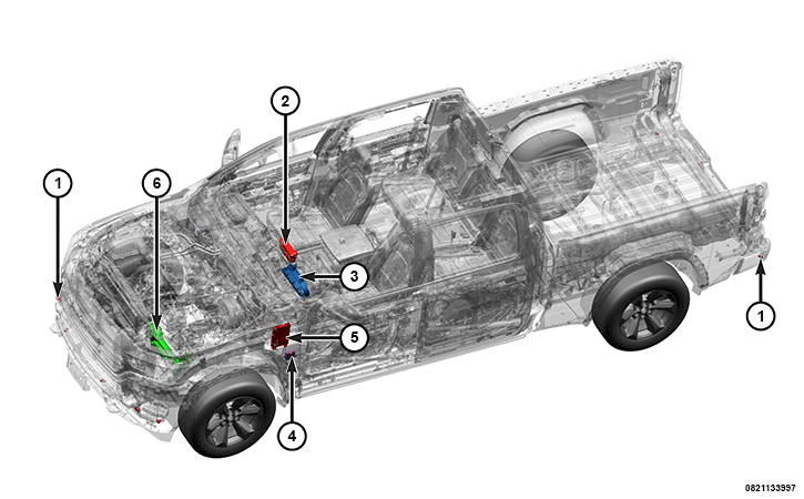 |
The Park Assist system uses the following components and modules:
Component Index
|
1. |
Front and Rear Park Assist (FRPA) Sensors (Working clockwise around the vehicle, the Left Front is sensor #1 and the Left Rear is sensor #12) |
|
2. |
|
|
3. |
|
|
4. |
|
|
5. |
|
|
6. |
|
|
- |
The FRPA system detects objects located in front of the vehicle and behind the vehicle within defined coverage zones. When an object is detected, the FRPA system provides an alert to the customer based on the selected customer configuration and the object's location and distance relative to the vehicle. The system assists the driver during parking by sensing obstacles situated outside the driver's field of view.
The information regarding the presence and distance of an obstacle is transmitted to the driver in the form of an audible alert and graphic display. The audible alert is pulsed at a rate dependent on distance to the obstacle.
OPERATION
Each time the park assist OFF switch is depressed the switch bank pod circuitry sends an electronic switch status message input to the BCM over the Controller Area Network - Interior High Speed (CAN-IHS) data bus. The BCM then relays an electronic switch request message to the PAM. The PAM responds to each switch request message by toggling the status of the appropriate FRPA sensors to enabled or disabled, then sends an electronic system status message back to the BCM over the CAN-IHS data bus as confirmation.
The BCM responds to the system status message by sending a message to the ICS over the CAN data bus to control the park assist Light Emitting Diode (LED) units so that they are illuminated only when appropriate while the status of the ignition is ON, and are extinguished when the status of the ignition is anything except ON. If the FRPA is disabled due to a monitored fault or failure, a press of the corresponding park assist OFF push button will result in the LED flashing on and off for about 5 seconds, then lighting solid.
When the Parallel and Perpendicular Parking Assist (PPPA) system is active, the FRPA system only provides audible alerts and, if enabled, autonomous braking. Once the PPPA maneuver has been competed, the FRPA system will revert back to its normal operation.
OPERATING CONDITIONS - The FRPA is active only when the ignition switch is in the ON or START positions and the transmission (manual or automatic) is in one of the following:
- REVERSE gear position and the vehicle speed is less than 11 km/h (7 mph).
- DRIVE or a forward gear position and the vehicle speed is less than 9 km/h (6 mph) on deceleration.
- DRIVE or a forward gear position and the vehicle speed is less than 11 km/h (7 mph) on acceleration.
DISABLE FEATURE - When the FRPA is disabled, a PARK ASSIST OFF status will be shown within the vehicle graphic within the IPC display whenever the gear selector lever is in the REVERSE position.
When the PAM monitors a problem in any of the FRPA circuits or components, it stores a fault code or Diagnostic Trouble Code (DTC) in its memory circuit, sends an electronic message to the IPC, and a SERVICE PARK ASSIST SYSTEM textual message is displayed in the IPC display.
When the FRPA button is pressed to ON, the ICS sends an output signal to the BCM. The BCM then relays an electronic switch request message to the PAM over the CAN data bus. The PAM responds to each switch request message by toggling the status of the appropriate FRPA feature from enabled to disabled, or from disabled to enabled, then sends an electronic system status message back to the BCM over the CAN data bus as confirmation.
Body Control Module (BCM)
The BCM is the gateway for CAN-IHS to CAN-Chassis (CAN-C) bus communications.
Inputs
- Receiving the ICS input request for FRPA ON/OFF requests
- Reverse gear status input from the Powertrain Control Module (PCM) obtained over the CAN bus from the Transmission Control Module (TCM)
Outputs
- Enabling and disabling the FRPA light
- Outputs the chime activation request
- Requests to the IPC to display the vehicle graphics layout on the IPC screen
- Gated PPPA switch state signal to the ICS and PAM
Display Screen Module (DSM)
The DSM can be used to enable the semi-automatic park and park assist system as well as the ParkSense™ camera activation. The DSM outputs the soft switch requests directly to the BCM for operation as well the ICS for lighting. The BCM gates the switch state to the PAM. The BCM also gates control behavior signal to the DCM in order to display the appropriate indicator.
Electronic Power Steering (EPS) Module
The EPS is used in the semi-automatic park and FRPA system to provide haptic feedback, or torque overlay to assist the vehicle operator. This only occurs when the sensors recognize that the vehicle is situated in the correct position to begin the steering maneuver for a parking slot. The EPS module will ramp assist to match a torque value being requested by the PAM. The EPS also looks for torque applied to the steering wheel to determine a "hands on wheel" condition. This condition needs to be met prior to any PPPA event.
Instrument Panel Cluster (IPC)
The visual warnings are provided in the IPC for when there is an object within 120 cm (47 in.) in front of the vehicle or 200 cm (78 in.) behind the vehicle. In drive, only the front is active and it is only displayed when the object is detected. In reverse, FRPA is active and the screen is requested at all times. The audible warning will change from intermittent beeps to a continuous tone as the vehicle comes to within 30 cm (12 in.).
During semi-automatic parking maneuver, the IPC will also display the drivers desired selection.
Inputs
- Display activation from the BCM
- Display graphic layouts from the BCM
- Park alerts from the BCM
- Chime activations from the BCM
- PAM system status from the BCM
- Above speed indication from the BCM
Outputs
- FRPA display
- FRPA Enable/Disable/Unavailable/User Disabled status
- PAM system faults
- Chime activations
Integrated Center Stack (ICS)
The FRPA Off switch is integral to the ICS which is located just below the radio. The switch push button is clearly identified with a white International Control and Display Symbol graphic for Parking Aid and the text OFF. An amber LED unit is illuminated behind a small clear plastic jewel-like lens in the FRPA OFF push button to give a visual indication whenever the park assist system has been manually disabled or if a system fault is monitored.
The status of the FRPA OFF switch is continually monitored by the circuitry within the ICS. The ICS receives battery voltage at all times on a fused battery feed circuit and has a path to ground at all times through the instrument panel wire harness. The inputs to and outputs from the ICS consist of electronic message communication with the BCM over the CAN data bus.
Inputs
- Receives the semi-automatic park and FRPA system lighting requests from the FRPA switch.
- Receives the PAM lighting control inputs from the BCM.
Outputs
- Sends the PAM switch status ON/OFF requests to the BCM.
- Sends the semi-automatic park and FRPA lighting command to the FRPA switch.
Park Assist Module (PAM)
The PAM is the central component of the FRPA. It supplies voltage to the FRPA sensors, receives and analyzes data from the sensors, calculates and communicates the proper display information to the BCM, performs system diagnostics, and communicates with other electronic modules in the vehicle or with a diagnostic scan tool over the CAN data bus. The module operates on battery voltage received through a fuse in the Power Distribution Center (PDC), and is grounded through a take out of the body wire harness.
The PAM receives a BCM gated input indicating that the PPPA system soft switch has been enabled.
Inputs
- Each FRPA sensor inputs to the PAM
- PAM operation mode from the BCM
- Steering wheel angle from the Steering Column Control Module (SCCM)
- Ignition status from the BCM
- Vehicle speed and wheel pulse information from the Antilock Brake System (ABS) module
- Reverse gear status from the BCM
- PAM alert mode from the BCM
Outputs
- Steering control output to the EPS
- Rear object detection information to the ABS module
- Power to each FRPA sensors
- PAM LED control status to the BCM
- Park chime type to the BCM to the IPC
- Park chime activation to the BCM to the IPC
- Park chime repetition rate to the BCM and the IPC
- PAM system fault to the BCM
- PAM above speed to the BCM
- Trigger signals to all of the FRPA sensors
Front and Rear Park Assist (FRPA) Sensors
Ultrasonic FRPA sensors located in the front and rear bumper fascia allow the FRPA to locate and identify the proximity of nearby obstacles. The FRPA sensors each receive battery current and ground in parallel from the PAM, but are each connected to individual dedicated serial bus communication circuits to the PAM. These sensors each generate ultrasonic sound pulses when triggered by the PAM, then signal the PAM when an echo of the reflected sound pulses is received. The detection distance range from the rear of the vehicle is about 200 cm (78 in.), and the detection range for the front of the vehicle is within 120 cm (47 in.). The detection area extends around both front and rear sides (corners) of the vehicle.
Inputs
Outputs
The park assist sensor numbering for vehicles equipped with parallel park assist starts at the front left as sensor #1 and travels clockwise to #12 at the rear left sensor.
For vehicles equipped with front park assist only, sensor #1 is the front left and sensor #6 is the front right.