Description
Blind Spot Monitoring With Rear Cross Path Detection
▸Contents: 08 - Electrical
8A - Audio/Video/Entertainment/Connectivity
- Description And Operation
- Technical SpecificationsTorque Specifications
ANTENNA, Bluetooth/WiFi
Media Hub
Removal and Installation
SWITCH, Remote Radio
8B - Chime/Buzzer/Driver Assist
- DISPLAY, Blind SpotRemoval And Installation
MODULE, Park Assist
SENSOR, Blind Spot
SENSOR, Park Assist
Removal and Installation
8C - Power Accessories
Universal Transmitter
- DescriptionUniversal Garage Door Opener
- Diagnosis and TestingHomelink® Transceiver
Standard Procedure
- Erasing Homelink® Transceiver Codes
- Programming Homelink® Transceiver Codes
- Reprogramming Homelink® Transceiver Codes
- Removal And Installation
8E - Electronic Control Modules
- Standard ProcedureImmobilizer Components And Replacement Guide
- Technical SpecificationsTorque Specifications
Amplifier (Amp)
- Description and OperationAmplifier
- Removal and InstallationAmplifier (Amp)
Communication
- DescriptionDescription And Operation
CONNECTOR, Data Link (DLC)
- Description and OperationData Link Connector (Dlc)
CONTROL UNIT, DEF Heater
- Description
- Removal and InstallationDef Heater Control Unit
MODULE, Active Air Dam (AADM)
- DescriptionActive Air Dam (Aad) Module
- Removal and InstallationActive Air Dam Module
MODULE, Active Damping Control (ADCM)
- Description and OperationActive Damping Control Module (Adcm)
- Removal And Installation
MODULE, Active Noise Cancellation (ANC)
- Description and OperationActive Noise Cancellation (Anc) Module
Removal and Installation
- Microphone-Front
- Microphone-Rear
- Active Noise Cancellation Module
MODULE, Active Vibration Cancellation (AVCM)
- Description and OperationActive Vibration Cancellation (Avc)
Removal and Installation
- Actuator
- Module
- Module ProgrammingAvc Programming
MODULE, Adaptive Front Lighting System (AFLS)
- DescriptionAdaptive Front Lighting System (Afls)
- Removal and InstallationAdaptive Front Lighting System Module (Afls)
MODULE, Air Suspension Control (ASCM)
- Description and OperationAir Suspension Control Module (Ascm)
- Removal and InstallationAir Suspension Control Module (Ascm)
MODULE, Anti-Lock Brake System (ABS)
- Description And Operation
- Removal and InstallationAnti-Lock Brake System (Abs) Module
- Module ProgrammingAbs
MODULE, Blind Spot (BSM)
- Description and OperationBlind Spot Monitor (Bsm)
- Removal and InstallationBlind Spot Module (Bsm)
MODULE, Body Control (BCM)
- Description and OperationBody Control Module (Bcm)
- Removal and InstallationBody Control Module (Bcm)
MODULE, Central Vision Processing (CVPM)
- DescriptionDescription And Operation
- Removal and InstallationCentral Vision Processing Module (Cvpm)
- Module ProgrammingCvpm Programming
MODULE, Comfort Rear Seat (CRSM)
- Description and OperationComfort Rear Seat Module (Crsm)
- Removal and InstallationComfort Rear Seat Module (Crsm)
MODULE, Comfort Seat and Wheel (CSWM)
- Description and OperationComfort Seat Wheel Module (Cswm)
Removal and Installation
- Base
- Tungsten
MODULE, Display Screen (DSM)
Description and Operation
- Display Screen Module
- Front Passenger Display Module
Removal and Installation
- 8.4 Inch Display
- 12 Inch Display
- Front Passenger Display Module
MODULE, Door (DDM/PDM)
- Description and OperationDoor Control Modules
- Removal and InstallationDoor Control Module
MODULE, Drivers Assistance System (DASM)
- Description and OperationDrivers Assistance System Module (Dasm)
- Removal and InstallationDriver Assistance System Module (Dasm)
- Module ProgrammingDriver Assistance System Module (Dasm) Calibration
MODULE, Drivetrain Control (DTCM)
- Description and OperationDrivetrain Control Module (Dtcm)
- Removal and InstallationDrivetrain Control Module (Dtcm)
MODULE, Electric Power Steering (EPS)
- Description and OperationElectric Power Steering (Eps) Module
- Removal and InstallationElectronic Power Steering (Eps) Module
MODULE, Electronic Shift (ESM)
- Description and OperationElectronic Shift Module (Esm)
- Removal and InstallationElectronic Shift Module (Esm)
MODULE, Fuel Pump Control
- Description and OperationFuel Pump Control Module
- Removal and InstallationFuel Pump Control Module (Fpcm)
MODULE, Global Telematics Box
- Description and OperationGlobal Telematics Box Module (Tbm2)
Removal and Installation
- Module
- Backup Battery
Module, Hvac
- Description and OperationHvac System
- Removal and InstallationHvac Module
MODULE, Instrument Panel Cluster (IPC)
- Description And Operation
Removal and Installation
- Instrument Panel Cluster
- Mask And Lens
MODULE, Integrated Center Stack (ICSM)
- Description and OperationIntegrated Center Stack (Ics) Module
- Removal and InstallationIntegrated Center Stack Module (Icsm)
MODULE, Integrated Trailer Brake (ITBM)
- Description And Operation
- Diagnosis And Testing
Removal and Installation
- Integrated Trailer Brake Module (Itbm)
- Integrated Trailer Brake Switch (Itbs)
MODULE, Keyless Ignition Node (KIN)
- Description and OperationKeyless Ignition Node (Kin)
- Removal and InstallationKeyless Ignition Node (Kin)
MODULE, Memory Seat (MSM)
- Description and OperationMemory Seat Module (Msm)
Removal and Installation
- Base
- Tungsten
MODULE, Occupant Classification (OCM)
- Description and OperationOccupant Classification Module (Ocm)
- Removal and InstallationOccupant Classification Module (Ocm)
Controller, Occupant Restraint (ORC)
- Description and OperationOccupant Restraint Control (Orc)
- Removal and InstallationOccupant Restraint Controller (Orc)
MODULE, Park Assist (PAM)
- DescriptionDescription And Operation
- Removal and InstallationPark Assist Module
- Module ProgrammingDisable/Enable Park Assist Functionality
MODULE, Power Side Step (PSSM)
- Description and OperationPower Side-Step Module (Pssm)
- Removal and InstallationPower Side Step Module
MODULE, Powertrain Control (PCM)
- Description and OperationPowertrain Control Module (Pcm)
Removal and Installation
- Diesel
- GPEC 2a
- Gpec V
Module Programming
- Pcm Programming
- Tlc Learn Procedure
MODULE, Radio Frequency (RF Hub)
- Description and OperationRadio Frequency Hub (Rf-Hub)
- Removal and InstallationRadio Frequency (Rf Hub) Module
Module Programming
- Key Fob Programming
- Programming The Rf-Hub And Key Fobs
MODULE, Seat Massage (SMM)
- Description and OperationSeat Massage Module
- Removal and InstallationSeat Massage Module
MODULE, Security Gateway (SGW)
- Description and OperationSecurity Gateway (Sgw) Module
- Removal and InstallationSecurity Gateway (Sgw) Module
MODULE, Steering Column Control (SCCM)
- Description and OperationSteering Column Control Module (Sccm)
- Removal and InstallationSteering Column Control Module (Sccm)
MODULE, Trailer CAN Gateway Module (TCGWM)
- DescriptionTrailer Can Gateway Module
- Removal and InstallationTrailer Can Gateway Module (Tgwm)
MODULE, Trailer Interface (TIM)
- DescriptionTrailer Interface Module (Tim)
- Removal and InstallationTrailer Interface Module (Tim)
MODULE, Trailer Reverse Steering Control (TRSCM)
- DescriptionTrailer Reverse Steering Control (Trsc)
- Removal and InstallationTrailer Reverse Steering Control Module (Trscm)
MODULE, Trailer Surround View Camera Module (STIM)
- DescriptionTrailer Surround View Camera Module (Stim)
- Removal and InstallationTrailer Surround View Camera Module (Stim)
MODULE, Trailer Tire Pressure (TTPM)
- DescriptionTrailer Tire Pressure Monitoring (Ttpm)
- Removal and InstallationTrailer Tire Pressure Monitor (Ttpm)
MODULE, Transmission Control (TCM)
- Description and OperationTransmission Control Module (Tcm)
- Removal and InstallationTransmission Control Module
Module Programming
- Programming The Transmission Control Module
- Tcm Adaptation - 850re / 8hp75
Radio
- Description And Operation
Removal and Installation
- Radio With Dsm
- Radio Without Dsm
8F - Engine Systems
Battery System
- Description and OperationLow Voltage Battery System
Diagnosis and Testing
- Diagnosis And Testing - Single Battery 12 Volt System
- Open Circuit Voltage Test
Technical Specifications
- Battery
- Torque Specifications - Battery System
Standard Procedure
- Ignition Off Draw Test - Gas/Diesel
- 12 Volt Battery Charging
- BATTERY DISCONNECT AND CONNECT - eTORQUE SYSTEM
Battery
- Removal and InstallationBattery
SENSOR, Intelligent Battery (IBS)
- Removal and InstallationIntelligent Battery Sensor (Ibs)
TRAY, Battery
- Removal and InstallationBattery Tray - Except 6.2l
Starting
Description and Operation
- Standard Starting
- Remote Start System
- Diagnosis and TestingStandard Starting System
- Technical SpecificationsTorque Specifications
ANTENNA, Remote Start
- Removal and InstallationRemote Start Antenna (Rsa)
BUTTON, Start/Stop
- Removal and InstallationStart/Stop Button
Starter
- Removal and InstallationStarter Motor
8G - Heated/Cooled Systems
Heated/Cooled Accessories
- Description And Operation
Diagnosis and Testing
- Heated Steering Wheel
- Ventilated Seats
MOTOR, Vented Front Seat Back
Removal and Installation
- Vented Front Seat Back Motor
- Vented Front Seat Cushion Motor
- Vented Rear Seat Back Motor 40%
- Vented Rear Seat Back Motor 60%
- Vented Rear Seat Cushion Motor 40%
- Vented Rear Seat Cushion Motor 60%
PAD, Vented Front Seat Back
Removal and Installation
- Vented Front Seat Back Pad
- Vented Front Seat Cushion Pad
- Vented Rear Seat Back Pad 40%
- Vented Rear Seat Back Pad 60%
- Vented Rear Seat Cushion Pad 40%
- Vented Rear Seat Cushion Pad 60%
SWITCH, Heated Steering Wheel
- Removal and InstallationHeated Steering Wheel Switch
SWITCH, Vented Seat
Removal and Installation
- Removal And Installation
- Vented Rear Seat Switch
WHEEL, Heated Steering
- Removal and InstallationHeated Steering Wheel
Heated Glass
- Description And Operation
- Diagnosis and TestingDiagnosis And Testing - Electric Backlight (Ebl) And Heated Mirror System
GRID, Defogger
- Standard ProcedureStandard Procedure - Grid Line And Terminal Repair
- Heated MirrorsDescription And Operation
Heated Seats
- Description And Operation
- Diagnosis and TestingDiagnosis And Testing - Heated Seat System
PAD, Heater
Removal and Installation
- Base
- Tungsten
- Base
- Tungsten
- Heater Rear Seat Back Pad
- Heater Rear Seat Cushion Pad
SWITCH, Heated Seat
Removal and Installation
- Front Seat Switch
- In Center Seat
- In Floor Console
8H - Horn
- Description And Operation
- Diagnosis and TestingDiagnosis And Testing - Horn System
- Technical SpecificationsTorque Specifications
Horn
- Diagnosis and TestingDiagnosis And Testing - Horn
- Removal and InstallationHorn
SWITCH, Horn
- Diagnosis and TestingDiagnosis And Testing - Horn Switch
- Removal And Installation
8J - Instrument Cluster
- Description and OperationInstrument Cluster And Switches
- Diagnosis and TestingInstrument Panel Cluster
- Standard ProcedureEnhanced Seatbelt Reminder Programming
Removal and Installation
- Instrument Panel Cluster
- Mask And Lens
DISPLAY, Heads Up
- Removal and InstallationHeads Up Display
MODULE, Trailer Reverse Steering Knob (TRSKM)
- Removal and InstallationTrailer Reverse Steering Knob Module (Trskm)
POD, Switch Bank
- Removal and InstallationSwitch Bank Pod
SWITCH, EVIC Control
- Removal and InstallationEvic Switch
8L - Lamps and Lighting
Lamps/Lighting - Exterior
- Description and OperationExterior Lamps And Lighting
- Diagnosis and TestingExterior Lamps And Lighting
- Standard ProcedureFront Lamp Aiming
- Technical SpecificationsTorque Specifications
Lamp
- Removal and InstallationTrailer Hitch Lamp
LAMP, Cargo
- Removal and InstallationCargo Lamp
LAMP, Center High Mounted Stop
Removal and Installation
- Bulb
- Center High Mounted Stop Lamp (Chmsl)
LAMP, Fog
Removal and Installation
- Bulb
- Lamp - Bulb
- Front Fog Lamp
- Lamp - Rebel/Trx
- Lamp - Tungsten
LAMP, License Plate
- Removal and InstallationLicense Plate Lamp
LAMP, Mirror
Removal and Installation
- Puddle Lamp
- Puddle Lamp Power Telescoping
- Puddle Lamp Tow Mirror Without Surround View
- Puddle Lamp Tow Mirror With Surround View
- Signal Lamp
- Signal Lamp Power Telescoping
- Signal Lamp Tow Mirror
- Signature Lamp Power Telescoping
- Spotter Lamp Power Telescoping
- Spotter Lamp Trailer Towing
LAMP, Park and Turn Signal
- Removal and InstallationPark And Turn Signal Lamp
LAMP, Ram Box
- Removal and InstallationRam Box Lamp
LAMP, Identification
Removal and Installation
- Front
- Rear
LAMP, Side Marker, Front
- Removal and InstallationFront Side Marker Lamp
LAMP, Side Marker, Rear
- Removal and InstallationRear Side Marker Lamp
LAMP, Tail Stop Turn
Removal and Installation
- Bulb
- Tail Lamp Assembly
SENSOR, Stop Lamp
- Removal and InstallationStop Lamp Sensor
SWITCH, Headlamp
- Removal and InstallationHeadlamp Switch
- SWITCH, MultifunctionRemoval And Installation
UNIT, Front Lamp
- Standard ProcedureLamp Lens Defogging
Removal and Installation
- Headlamp Unit
- Headlamp Bulbs
Lamps/Lighting - Interior
- Description And Operation
- Diagnosis and TestingDiagnosis And Testing - Interior Lighting
LAMP, Courtesy
Removal and Installation
- Cupholder Overhead
- Console Lid
- Door Handle
- Door Map
- Door Mid Bin
- Footwell
- Instrument Panel
- Seat
LAMP, Glove Box
- Removal and InstallationLamp/Switch
LAMP, Dome
- Removal and InstallationDome Lamp
8N - Power Systems
Power Locks
- Description And Operation
- Diagnosis and TestingPower Locks
ANTENNA, Passive Entry
Removal and Installation
- Passive Entry Antenna - Center Cab
- Rear Cab
- Rear Door
- Rear Box
SWITCH, Lock
- Removal and InstallationLock Switch
- SWITCH, Tailgate ReleaseRemoval And Installation
TRANSMITTER, Integrated Key FOB
Diagnosis and Testing
- Keyfob Transmitter Battery
- Keyfob Transmitter
- Standard ProcedureKey Fob Programming
Power Mirrors
Description and Operation
- Exterior Power Mirrors
- Interior Power Mirrors
- MIRROR, Automatic Day and NightRemoval And Installation
MIRROR, Outside Rearview
- Removal and InstallationOutside Rearview Mirror
SWITCH, Mirror
- Diagnosis and TestingPower Mirror Switch
- Removal And Installation
Power Seats
Description and Operation
- Power Seats
- Memory Seats
- Diagnosis and TestingPower Seat System
MOTOR, Lumbar
- Removal and InstallationLumbar Motor
MOTOR, Seat
Removal and Installation
- Power Seat Motor
- Tungsten - Seat Cushion Extension
- Tungsten - Seat Fore-Aft
- Tungsten - Seat Tilt
- Tungsten - Seat Up-Down
SWITCH, Lumbar Control
- Removal and InstallationLumbar Control Switch
SWITCH, Memory
- Removal and InstallationMemory Switch
SWITCH, Seat, Power
Removal and Installation
- Base
- Tungsten
Power Side Step
- DescriptionPower Side Step
- Diagnosis and TestingDiagnosis And Testing - Power Side Steps
MOTOR, Power Side Step
- Removal and InstallationPower Side Step Motor
Power Tailgate
MODULE, Tailgate Control
- Removal and InstallationTailgate Control Module
Power Top, Sunroof
- Description And Operation
Diagnosis and Testing
- Diagnosis And Testing - Single Pane Power Sunroof System
- Diagnosis And Testing - Dual Pane Power Sunroof System
- Technical SpecificationsTorque Specifications
MOTOR, Sunroof
Standard Procedure
- Dual Pane Sunroof Calibrations
- Single Pane Sunroof Calibrations
- Sunroof Or Sunshade Obstacle Detection Override
Removal and Installation
- Dual Pane Motor
- Single Pane Motor
MOTOR, Sunroof Shade, Dual Pane
- Removal and InstallationDual Pane Sunroof Shade Motor
- SWITCH, SunroofRemoval And Installation
Power Windows
- Description and OperationPower Windows
- Diagnosis and TestingPower Windows
MOTOR, Window Regulator
- Removal and InstallationWindow Regulator Motor
SWITCH, Power Window
- Diagnosis and TestingDiagnosis And Testing - Power Window Switches
- Removal and InstallationPower Window Switch
8P - Speed Control
Description and Operation
- Conventional Cruise Control
- Adaptive Cruise Control With Stop And Go
SWITCH, Speed Control
- Removal and InstallationSpeed Control Switch
8Q - Vehicle Theft Security
Description and Operation
- Sentry Key Immobilizer System
- Vehicle Theft Alarm
- Diagnosis and TestingKey Fob Testing
SWITCH, Hood Ajar
- Diagnosis and TestingDiagnosis And Testing - Hood Ajar Switch
- Removal and InstallationHood Ajar Switch
8R - Wipers/Washers
- Description And Operation
- Diagnosis and TestingFront Wiper System
- Technical SpecificationsTorque Specifications
Cleaning
- Washer System Cleaning
- Wiper System Cleaning
Inspection
- Washer System Inspection
- Wiper System Inspection
ARM, Wiper
- Removal and InstallationWiper Arm
BLADE, Wiper
- Removal and InstallationWiper Blade
LINKAGE, Wiper Arm
- Removal and InstallationWiper Arm Linkage
MODULE, Humidity Rain Light Sensor
Standard Procedure
- Protective Cap Removal
- Silicone Gelatin Pad Replacement
- Removal and InstallationHumidity Rain Light Sensor Module (Hrlsm)
MOTOR, Wiper
- Removal and InstallationWiper Motor
NOZZLE, Washer
Removal and Installation
- Washer Nozzle
- Trx Washer Nozzle
PUMP, Windshield Washer
- Removal and InstallationWindshield Washer Pump
RESERVOIR, Windshield Washer
- Removal and InstallationWindshield Washer Reservoir
SWITCH, Multifunction, Left
- Removal and InstallationLeft Multifunction Switch
SWITCH, Washer Fluid Level
- Removal and InstallationWasher Fluid Level Switch
8T - Navigation/Telecommunication
Description and Operation
- Hands Free Phone
- Navigation
- Uconnect + Siriusxm Guardian
Diagnosis and Testing
- Diagnosis And Testing - Hands Free Phone
- Diagnosis And Testing - Navigation
- Diagnosis And Testing - Uconnect + Siriusxm Guardian
Standard Procedure
- Navigation System - Restore Or Update
- Uconnect + Siriusxm Guardian System - Reinstall Applications
- Uconnect® + Siriusxm® Guardian™ System - Remove Accounts
ANTENNA, Long-Term Evolution 2 (LTE2)
- Diagnosis and TestingDiagnosis And Testing - Cellular Antenna
- Removal and InstallationLong Term Evolution 2 (Lte2) Antenna
ANTENNA, Navigation
- Diagnosis and TestingDiagnosis And Testing - Navigation Antenna
- Removal and InstallationNavigation Antenna
Microphone
- Diagnosis and TestingDiagnosis And Testing - Microphone
- Removal and InstallationMicrophone
8W - Power Distribution
- Description And Operation
- Diagnosis and TestingWireless Charging Pad Module
- Technical SpecificationsTorque Specifications
CENTER, Power Distribution (PDC)
Removal and Installation
- Power Distribution Center - Front
- Power Distribution Center - Interior
MODULE, Power Inverter
- Removal and InstallationPower Inverter Module (Pim)
MODULE, Wireless Charging Pad
Removal and Installation
- Wireless Charging Pad Module
- Wireless Charging Pad Module-Trx
OUTLET, Power
- Diagnosis and TestingDiagnosis And Testing - 115 V Power Outlet
Removal and Installation
- 12 Volt Outlet – Instrument Panel
- 115 Volt Outlet – Front
- 115 Volt Outlet – Ram Box
- 115 Volt Outlet - Rear
- Switch – Rambox 115 Volt Outlet
- Usb Charge Port - Console Lid
- Usb Charge Port - Rear Console
DESCRIPTION
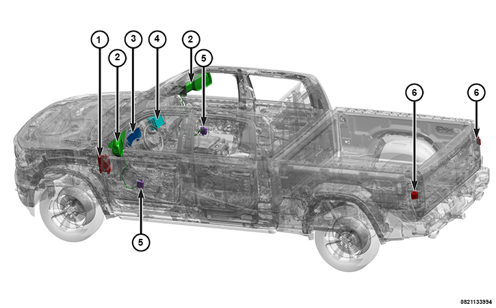 |
The Blind Spot Monitoring (BSM) with Rear Cross Path (RCP) Detection system can consist of the following components:
Component Index
|
1. |
|
|
2. |
|
|
3. |
|
|
4. |
|
|
5. |
Door Control Module (DCM) - Driver Door Module (DDM) and Passenger Door Module (PDM) |
|
6. |
Blind Spot Module (BSM) - Right Blind Spot Sensor (RBSS) and Left Blind Spot Sensor (LBSS) |
|
– |
The BSM system, if enabled in the radio, monitors the rear blind zones on both sides of the vehicle using radar detection. If a vehicle is sensed in one of the blind spot zones, the driver will be notified by a blind spot indicator lamp that illuminates an icon on the outside rear view mirror on the side of the vehicles where the vehicle is detected.
The RCP detection monitors for vehicles perpendicular to the rear of the vehicle when the host vehicle is shifted into R everse. The system provides feedback to the driver by using audible chimes and visual icons. The visual and audible alerts correspond to the side of the approaching vehicle.
The BSM system:
- Monitors the vehicle's blind spots.
- Notifies the driver when another vehicle is present.
- Uses radar sensors located in the sides of the tail lamps.
- Illuminates icons in the outside review mirror glass.
- Chimes when the driver selects a turn signal on the side that has a vehicle in the zone.
- Notifies driver of vehicles in the blind spot areas when changing lanes, passing vehicles, or if being passed.
- RCP detection notifies the driver via a chime if a vehicle is crossing the host vehicle's path when the host vehicle is in reverse.
- The driver can turn the system OFF, ON or ON with Chime. (Note: In RCP mode the chime can not be disabled it is always active)
OPERATION
When the vehicle speed exceeds 10 km/h (6 mph) and the Left Blind Spot Sensor (LBSS) or the Right Blind Spot Sensor (RBSS) detects an object within 24 km/h (15 mph) of the vehicle speed passing through the monitored zone from the rear of the vehicle, the LBSS sensors will request a blind spot indicator request to the DDM. The DDM or PDM controls the indicator lamp through a Pulse Width Modulated (PWM) circuit to the mirror on the side of the vehicle that the object is detected. If the driver attempts to enter the zone where the object has been detected and with the turn signal activated, the sensor will send out two additional requests over the Controller Area Network - Interior High Speed (CAN-IHS) bus to the BCM. The BCM then sends these messages to:
- The Radio, if the vehicle is NOT equipped with an Amplifier (AMP), to mute audio speakers.
- Or, If equipped. to the AMP to request a auditory chime.
There are three operating modes for the BSM system:
- OFF: All visual and audible alerts related to objects of interest in the blind sport zone are suppressed.
- ON with blind spot indicator only
- ON with blind spot indicator and chimes
Rear Cross Path (RCP) detection system:
- Uses the LED icons on the outside mirrors to warn of vehicles approaching. The alert corresponds to the side that the vehicle is approaching from.
- Is activated when the vehicle is in R everse gear and the blind spot system is enabled to ON or ON with Chime selected in the Radio options menu.
The RCP detection system monitors the rear detection zones for vehicles that are moving toward the sides of the vehicle with a minimum speed of 13 km/h (8 mph).
Blind Spot Indicator Lamp - Exterior Rearview Mirror Glass
Commanded to illuminate by a hardwired PWM input from the corresponding DCM when either the LBSS or the RBSS detect a vehicle in the blind spot zone.
Blind Spot Module (BSM) - Right Blind Spot Sensor (RBSS) and Left Blind Spot Sensor (LBSS)
- The BSM system used in this vehicle has two control modules, each internal to the sensor mounted on the inside of the tail lamp assembly. The RBSS is mounted to the backside of the right tail lamp assembly and can be serviced separately from the lamp assembly. The LBSS is mounted to the backside of the left tail lamp assembly and can be serviced separately from the lamp assembly.
- Each of the sensors are independent control units.
- The LBSS is the master configuration node of the BSM system.
- Each sensor receives a fused ignition RUN power output.
- Each Tail Lamp Assembly contains multiple ground circuits. The Left Tail Lamp Assembly has three ground circuits and the Right Tail Lamp Assembly has four ground circuits. The forth ground circuit is used as a trigger to identify what side of the vehicle the blind spot sensor is located.
- Each sensor provides a request to their respective side DCM to provide a PWM hardwired output to enable blind spot indicator lamp on the mirror glass.
- Each sensor is also controls the dimming light strategy for the blind spot indicator lamp icon via the DCM for each mirror.
- Each sensor activates a bulb-check for approximately 0.6 seconds upon power up for each mirrors blind spot indicator lamp icon.
- If the sensors are blocked, the LBSS is responsible for sending a signal to the IPC to enable the "Blind Spot Temporarily Unavailable System Blocked" message as well as activating both blind spot indicator lamp icons in the mirrors via the DCM.
- The LBSS is responsible for sending the directional chime request for each chime warning event to the BCM. The BCM gates the requests to the IPC for display to the vehicle operator.
- The RCP detection zone covers a zone approximately one lane on both sides of the vehicle 3.2 meters (10 ft.) and extends from the driver's seat to between 3 and 7 meters (10 ft.) behind the rear fascia depending of the speed of the vehicle.
Body Control Module (BCM)
The BCM performs the gateway function from the CAN-IHS to the CAN-Chassis (CAN-C) network. The BCM receives BSM warning messages from the LBSS and will gate the signal and forward it to the IPC for display. The BCM also receives the request to mute that audio which it gates to the Radio, or if equipped, to the AMP. If equipped with an AMP, a chime will sound.
The BCM also provides fuse protected power to the LBSS and RBSS.
Door Control Module (DCM) - Driver Door Module (DDM) and Passenger Door Module (PDM)
The DDM receives input requests from the LBSS for blind spot indicator illumination. The DCM acknowledges these request and will provide a PWM hardiwred signal to the mirror to illuminate the icon. If the request is for the passenger side icon illumination, the DDM sends this request directly to the PDM which handles the illumination process.
Instrument Panel Cluster (IPC)
The IPC is responsible for displaying temporary unavailable and service warnings to the customer. These are generated by the LBSS and sent to the BCM. The BCM gates this message to the IPC for display.
Radio
The Radio, if the vehicle is NOT equipped with an Amplifier, will mute the audio speakers during alert events. If equipped with an AMP, a chime will sound. These events are bussed from the BCM.
Within the customer programmable options menu is the ability to activate the turn signal blind spot camera view. When a turn signal request is recognized, the radio sends the activation signal to the IPC to display the camera view.
Trailer Merge Assist
| NOTE: |
When Trailer Merge Assist is activated, Rear Cross Path is disabled. |
Trailer Merge Assist is a function of the Blind Spot Monitoring (BSM) system that extends the blind spot zone to work while pulling a trailer. Trailer Merge Assist consists of three sub functions:
Automatic Trailer Detection - There are two modes of operation for the detection of the trailer length:
- Automatic Mode — When “Auto Mode” is selected, the system will use the blind spot sensors to automatically determine the presence and length of a trailer. The presence of a trailer will be detected using the blind spot radar within 90 seconds of forward movement of the vehicle. The vehicle must be moving above 6 mph (10 km/h) to activate the feature. Once the trailer has been detected, the system will default to the maximum blind spot zone until the length has been verified. You will see “Auto” in the instrument panel cluster.
- Max Mode — When “Max Mode” is selected, the system will default to the maximum blind spot zone regardless of what size trailer is attached.
The setting that is selected is stored when the ignition is placed in the OFF position. To change this setting, it must be selected through the Uconnect Settings.
Trailer Length Detection - Once the trailer presence has been established. The trailer length will be established (by making a 90 degree turn) and then the trailer length category (example 10-20 ft. (3 m to 6 m)) will be displayed. This can take up to 30 seconds after completing the turn. During the same ignition cycle, if the vehicle is at a standstill for a minimum of 90 seconds, a new “trailer detection request” is enabled by the system once the vehicle resumes motion.
Maximum length supported by the Trailer Merge Assist feature is 39.5 ft. (12 m). Trailer length is considered the forward most portion of the trailer hitch to the rearward most portion of the body, bumper, or ramp of the trailer.
Maximum width supported by the Trailer Merge Assist feature is 8.5 ft. (2.59 m). Trailer width is measured at the widest portion of the trailer and may include wheels, tires, finders, or rails.
Fifth wheel or gooseneck trailers are not supported by Trailer Merge Assist.
Trailer Length Detection - Trailer length will be identified and placed into one of the following categories:
- Trailer length up to 10 ft. (3 m) — Blind spot zone will be adjusted to 10 ft. (3 m).
- Trailer length between 20 ft. to 30 ft. (6 m to 9 m) — Blind spot zone will be adjusted to 30 ft. (9 m).
- Trailer length between 30 ft. and 39.5 ft. (9 m to 12 m) — Blind spot zone will be adjusted to MAX distance.
Trailer length is determined within +/- 3 ft. (1 m) of actual length. Trailers that are the same size as the category limit, 10/20/30 ft. (3/6/9 m), could be subject to being placed in the category above or below the correct one.
Trailer Merge Warning - Trailer Merge Warning is the extension of the blind spot function to cover the length of the trailer, plus a safety margin, to warn the driver when there is a vehicle in the adjacent lane. The driver is alerted by the illumination of the BSM warning light located in the outside mirror on the side the other vehicle is detected. In addition, an audible (chime) alert will be heard and radio volume reduced.