Description
Air Suspension
▸Contents: 02 - Front Suspension
- Special Tools
Air Suspension
- Warning
- DescriptionAir Suspension
- Diagnosis And Testing
Standard Procedure
- Technical SpecificationsTorque Specifications
Air Line
COMPRESSOR ASSEMBLY, Air Suspension
HOSE ASSEMBLY, Air Suspension
RESERVOIR, Air Suspension
SENSOR, Height
Removal and Installation
Active Damping Suspension
- DescriptionDescription And Operation
SENSOR, Active Damping
Removal and Installation
- Front
- Rear
SENSOR, Height
Removal and Installation
- Front
- Rear
SHOCK ABSORBER, Active Damping
Removal and Installation
- Removal
- Removal
Wheel Alignment
- Diagnosis And Testing
Standard Procedure
- Alignment
- Curb Height Measurement
- Technical SpecificationsSpecifications
Front, Independent Front Suspension
- Description and OperationFront Suspension
Diagnosis and Testing
- Diagnosis And Testing
- Shock/Strut Diagnosis
- Technical SpecificationsTorque Specifications
ARM, Lower Control
Removal and Installation
- Lower Control Arm Without Trx
- Lower Control Arm With Trx
ARM, Upper Control
Removal and Installation
- Upper Control Arm Without Trx
- Upper Control Arm With Trx
BALL JOINT, Suspension, Lower
- Diagnosis And Testing
- Removal and InstallationLower Ball Joint
BALL JOINT, Suspension, Upper
- Diagnosis And Testing
- Removal and InstallationUpper Ball Joint
Hub And Bearing
- Diagnosis and TestingDiagnosis And Testing - Hub And Bearing Noise
- Removal and InstallationHub And Bearing
KNUCKLE, Steering
- Removal and InstallationSteering Knuckle
LINK, Stabilizer Bar
Removal and Installation
- Stabilizer Bar Link
- Stabilizer Bar Link - Trx/Rumblebee
SHOCK ABSORBER, Suspension
Removal and Installation
- Coil Over
- Air Suspension
- Coil Over With Trx
SPRING, Front
Removal and Installation
- Front Coil Spring
- Air Spring
STABILIZER BAR, Front
- Removal and InstallationFront Stabilizer Bar
DESCRIPTION
| WARNING: |
All pressurized air suspension components contain high pressure air (up to 220 psig). Use extreme caution when inspecting for leaks. Wear safety goggles and adequate protective clothing when inspecting or servicing the air suspension system. A sudden release of air under this amount of pressure can cause possible serious or fatal injury. |
| WARNING: |
Before performing any service on the air suspension system, the system must be disabled to prevent the system from changing ride height. Before any given component is to be serviced it must be deflated. Servicing the air suspension system without the system disabled, or with pressure in any specific component, can cause possible serious or fatal injury. |
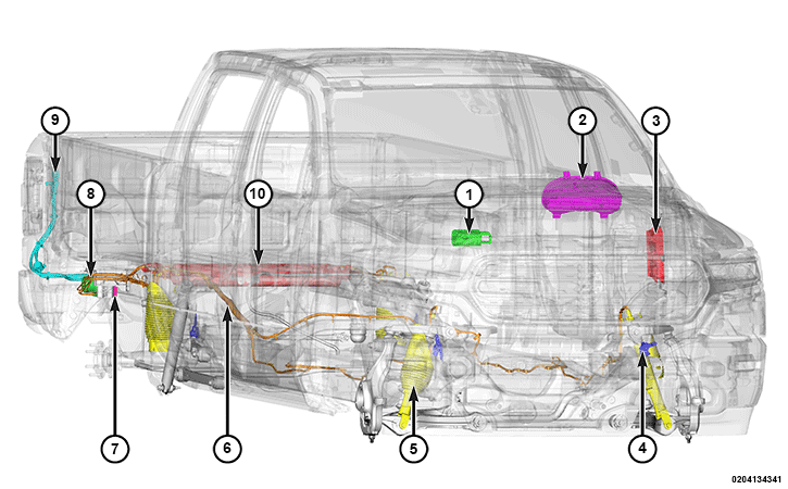 |
The Air Suspension System consists of the following major components:
Component Index
|
1. |
|
|
2. |
|
|
3. |
|
|
4. |
|
|
5. |
|
|
6. |
|
|
7. |
Air Suspension Control Module (ASCM) – integral to the Air Compressor |
|
8. |
Air Compressor – integral to the ASCM |
|
9. |
|
|
10. |
OPERATION
The air suspension system automatically or manually (operator control) lowers and lifts the vehicle using rear air springs and front air spring and shock assemblies. The air suspension system uses multiple integrated components in various areas of the vehicle to accomplish this.
| NOTE: |
The air suspension system can be disabled and enabled by using the Display Screen Module (DSM) in the vehicle under tire jack mode, which is the preferred method. If the disable level control routine in the scan tool is used it will only disable the level control (automatic and manual) for that ignition cycle. The air suspension system can also be enabled by driving the vehicle above 8 km/h (5 mph). The air suspension should be disabled prior to lifting the vehicle or performing any work. |
| NOTE: |
The air suspension system will not lower if any of the doors or the tailgate is open (normal operation) or the engine is not running. Doors and tailgate status are ignored when using a scan tool. |
| NOTE: |
When the ASCM or any height sensor is replaced the ASCM will need to be initialized using a scan tool. Refer to the appropriate installation procedure for specific instructions. |
Air Suspension System Refilling
For information about the complete system fill procedure (Refer to 02 - Front Suspension/Air Suspension/Standard Procedure) .
Changing Ride Height
When changing ride height using the up and down switch, ride height can only be changed while the air suspension system is in normal operating conditions. Air suspension system normal operating conditions are as follows:
- Diagnostic scan tool disconnected
- All doors closed
- Engine running
- Minimum battery voltage greater than 10.5 volts
When changing ride height using a scan tool, ride height can be changed regardless of the engine state (running or not), doors (open or closed). The only condition necessary is that battery voltage must be greater than 10.5 volts.
Ride Heights For Suspension Measurement Or Adjustment
When checking or performing the wheel alignment, the air suspension system must be at Normal Ride Height (NRH). When measuring curb height, the air suspension system must be at NRH.
Manual Control
An up and down switch is located in the switch bank pod for control of the system. When the user presses the up and down switch to manually raise or lower the vehicle height the Electronic Vehicle Information Center (EVIC) displays a vehicle "up" or "down" message icon and a LED indicator on the switch changes position. The EVIC displays the current position of the vehicle when it is achieved. When lowering the vehicle, the front is always first to move. When raising the vehicle, the rear is always the first to move. When the ASCM receives a command to change the vehicle more than one ride height position the action is performed in multiple steps. If request to change by two positions the rear will raise one position, then the front will raise one position, the rear again raises one position, then the front will raise to the final position. If requested to lower more than one position the same steps happen, EXCEPT the front moves first. This multi-step motion controls the angle the headlights are projected by controlling the pitch of the vehicle, keeping them from going above their normal projection plane.
There are five predetermined manual height settings; Normal Ride Height (NRH), two above and two below NRH. The predetermined vehicle heights (above or below NRH) are as follows:
|
MODEL |
FRONT |
|---|---|
|
Off Road 2 |
+ 51 mm (2.0 in.) |
|
Off Road 1 |
+ 30 mm (1.2 in.) |
|
Aero Mode |
- 28 mm (-1.1 in.) |
|
Park Mode |
- 53 mm (-2.1 in.) |
Air Compressor
The air compressor is powered by an electric 12-volt motor and is mounted outside the frame rail in the right rear of the vehicle. The air compressor features redundant air pressure sensors, which may aid in diagnosis.
The air compressor is serviced as an assembly with the ASCM and bracket. If replacement of the air compressor is necessary, (Refer to 02 - Front Suspension/Air Suspension/COMPRESSOR ASSEMBLY, Air Suspension/Removal and Installation) .
Air Hoses
Air hoses facilitate the venting or intake of atmospheric air and are located in the right rear tail lamp area.
Air Lines
Air lines transport air throughout the air suspension system.
Air Reservoir
The air reservoir is a dual aluminum cylinder design and is mounted between the frame rails under the pickup box. The air reservoir houses the compressed air which is used to raise and lower pressure in the air springs in turn affecting the ride height.
Air Spring
Air springs are positioned at each of the four corners of the suspension system and affect the vehicle curb height based on pressurized air which is transferred into or out of the air spring. The rear air springs feature three serviceable upper retaining clips.
Air Suspension Control Module (ASCM)
This air suspension system is a four-corner closed system. The system consists of four air springs, air reservoir, air lines which connect these components together, four height sensors, integrated module (which includes ASCM, air compressor, pressure sensor, and temperature sensor), and the air suspension switch which is integral to the switch bank pod. The main purpose of the system is to adjust the vehicle ride height. During any height level change, stored pressurized air is moved back and forth between the system reservoir and the four air springs. The system utilizes an air suspension switch which allows the customer to select different ride height levels. The vehicle will move to the requested ride height level if the vehicle speed is within the required range. This system is equipped with the following five manual ride height levels:
This system has automatic ride height which lowers the vehicle to Aero level based on vehicle speed. The ASCM controls the air suspension system and performs the logic for the customer's input requests. The ASCM automatically changes the vehicle ride height if the current level is outside the required vehicle speed range. The ASCM automatically adjusts vehicle ride height to compensate for vehicle loads.
CAN-C Inputs
- Air suspension switch state.
- Battery voltage measured at the terminals.
- Trailer connection status.
- Vehicle configuration.
- Averaged ambient temperature.
- Engine running state.
- Starter motor running.
- RFHM Basic request.
- Driving program display code.
- Commanded ignition switch status.
- Ignition run active for remote start.
- Current Gear.
- Vehicle longitudinal acceleration.
- Vehicle lateral acceleration.
- Shipping status.
- Ambient air pressure.
- Steering wheel angle sensor status.
- Steering wheel angle.
- Door ajar.
- Vehicle speed.
Hardwire Input
The ASCM is serviced as an assembly with the air compressor and bracket. If replacement of the ASCM is necessary, (Refer to 02 - Front Suspension/Air Suspension/COMPRESSOR ASSEMBLY, Air Suspension/Removal and Installation) .
Body Control Module (BCM)
The BCM separates the branches of the bus networking systems, the BCM must act as a gateway module to allow communication between the different bus networks. The BCM will translate and share messages among all modules on the following bus networks. The BCM is the configuration master for the vehicle. As the configuration master, the BCM broadcasts configuration data over the bus whenever the ignition is in the RUN state.
LIN Inputs
LIN Outputs
CAN-C Inputs
- Remote start request.
- Vehicle configuration.
- ASCM status.
- Height sensor levels.
- Wheel alignment level enabled.
- Transport mode enabled.
- ASCM warning messages.
- Request for off road 1 indicator.
- Request for off road 2 indicator.
- Request for normal indicator.
- Request for exit (Trailer_ HD) indicator.
- Target level.
- Aero mode disable/enable.
- ASCM remote lowering status.
- Request for AERO 1 indicator.
CAN-C Outputs
CAN-IHS Outputs
- Height sensor levels.
- Air suspension status.
- Wheel alignment level enabled.
- Tire jack mode.
- ASCM warning messages.
- Transport mode enabled.
- Aero mode disable/enable.
Height Sensor
The ASCM reads the four ride height sensor inputs (one near each of the wheels) which report the relative distance between the frame and the suspension. The ASCM uses these readings when determining the current vehicle height which has a diagnostic range between -100 mm from jounce to 153 mm rebound before any leveling. In addition, if any leveling is required, the ASCM sends the sensor signals on the CAN-C.
Hardwire Output
Instrument Panel Cluster (IPC)
The Electronic Vehicle Information Center (EVIC) is integral to the IPC, and the EVIC displays air suspension status messages.
CAN-C Inputs
- Commanded ignition switch status.
- Vehicle configuration.
- Air suspension status.
- Air suspension status for display.
- ASCM HMI status.
- Service air suspension.
- Loss of function - system fault.
- Loading level.
Switch Bank Pod
The switch bank pod is located in the center of the instrument panel below the Display Screen Module (DSM). The ride height switch in integral to the switch bank pod.
LIN Inputs
LIN outputs