Standard Procedure
Standard Procedure - Air Line Repair
▸Contents: 02 - Front Suspension
- Special Tools
Air Suspension
- Warning
- DescriptionAir Suspension
- Diagnosis And Testing
Standard Procedure
- Technical SpecificationsTorque Specifications
Air Line
COMPRESSOR ASSEMBLY, Air Suspension
HOSE ASSEMBLY, Air Suspension
RESERVOIR, Air Suspension
SENSOR, Height
Removal and Installation
Active Damping Suspension
- DescriptionDescription And Operation
SENSOR, Active Damping
Removal and Installation
- Front
- Rear
SENSOR, Height
Removal and Installation
- Front
- Rear
SHOCK ABSORBER, Active Damping
Removal and Installation
- Removal
- Removal
Wheel Alignment
- Diagnosis And Testing
Standard Procedure
- Alignment
- Curb Height Measurement
- Technical SpecificationsSpecifications
Front, Independent Front Suspension
- Description and OperationFront Suspension
Diagnosis and Testing
- Diagnosis And Testing
- Shock/Strut Diagnosis
- Technical SpecificationsTorque Specifications
ARM, Lower Control
Removal and Installation
- Lower Control Arm Without Trx
- Lower Control Arm With Trx
ARM, Upper Control
Removal and Installation
- Upper Control Arm Without Trx
- Upper Control Arm With Trx
BALL JOINT, Suspension, Lower
- Diagnosis And Testing
- Removal and InstallationLower Ball Joint
BALL JOINT, Suspension, Upper
- Diagnosis And Testing
- Removal and InstallationUpper Ball Joint
Hub And Bearing
- Diagnosis and TestingDiagnosis And Testing - Hub And Bearing Noise
- Removal and InstallationHub And Bearing
KNUCKLE, Steering
- Removal and InstallationSteering Knuckle
LINK, Stabilizer Bar
Removal and Installation
- Stabilizer Bar Link
- Stabilizer Bar Link - Trx/Rumblebee
SHOCK ABSORBER, Suspension
Removal and Installation
- Coil Over
- Air Suspension
- Coil Over With Trx
SPRING, Front
Removal and Installation
- Front Coil Spring
- Air Spring
STABILIZER BAR, Front
- Removal and InstallationFront Stabilizer Bar
| WARNING: |
All pressurized air suspension components contain high pressure air (up to 220 psig). Use extreme caution when inspecting for leaks. Wear safety goggles and adequate protective clothing when inspecting or servicing the air suspension system. A sudden release of air under this amount of pressure can cause possible serious or fatal injury. |
| WARNING: |
Before performing any service on the air suspension system, the system must be disabled to prevent the system from changing ride height. Before any given component is to be serviced it must be deflated. Servicing the air suspension system without the system disabled, or with pressure in any specific component, can cause possible serious or fatal injury. |
| NOTE: |
The air suspension system can be disabled and enabled by using the Display Screen Module (DSM) in the vehicle under tire jack mode which is the preferred method. If the disable level control routine in the scan tool is used it will only disable the level control (automatic and manual) for that ignition cycle. The air suspension system can also be enabled by driving the vehicle above 5 mph. The air suspension should be disabled prior to lifting the vehicle or performing any work. |
| NOTE: |
A maximum of 7 mm (0.275 in.) is allowed between the ends of the air line inside the air suspension union after a repair. If after the damaged area of the air line is removed and the two ends of the air line are more than 7 mm (0.275 in.) apart, the air line must be replaced. |
Air lines can be repaired for a hole or puncture; however if a line is cracked or crushed the entire line must be replaced.
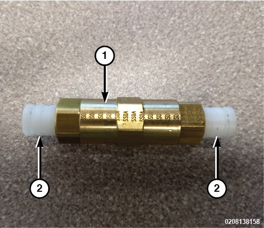 |
|
|
| 1 - Brass Air Suspension Union |
| 2 - Plastic Plug |
To repair a damaged air suspension air line, use a brass air suspension union and adhere to the following guidelines:
- A brass air suspension union comes fully assembled and is intended for use without any disassembly.
- There are two plastic plugs inserted into the union to keep out moisture and debris and to retain alignment of the line retainer inside the union.
- Do not remove the plastic plugs until ready to insert the line for repair.
- There are two O-rings inside and one O-ring on the threaded area of the nut on both ends of the union.
- Inside the union, between the body and the nut is a line retainer that locks the line in place when the line is pushed all the way into the union and then pulled.
- The pulling action on the air line is what locks the line into place.
- Raise and support the vehicle (Refer to 04 - Vehicle Quick Reference/Hoisting - Standard Procedure) .
- With a scan tool, using the routines under Air Suspension Control Module (ASCM), perform the following:
- Access the air line as necessary so that approximately 305 mm (12.0 in.) of line is accessible around the damaged area.
- Clean the air line with mild soapy water and thoroughly dry.
NOTE: Care must be taken when cutting the air line so that no ridge is created on the surface of the air line, and that the air line is not crushed into an oval shape or the air line adapter O-ring will not hold pressure.
- Using air line cutters, carefully cut the air line on each side of the damaged area removing no more than 7 mm (0.275 in.).
- Remove one plastic plug and insert the air line fully into the union.
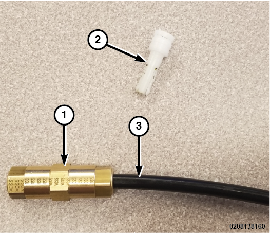
1 - Union 2 - Plastic Plug 3 - Air Line - Remove the remaining plug and insert the air line fully into the union.
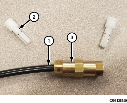
1 - Air Line 2 - Plastic Plug 3 - Union - Grasp the air line on both sides of the union and pull to seat the retainer and properly seal the union and lines.
- With a scan tool, using the routines under the Air Suspension Control Module (ASCM), perform the following:
- Fill Spring From Reservoir or if the reservoir air line was serviced, set the mode switch to normal ride height.
- Run the Air Mass Calculation routine on the air suspension system.
- If necessary, add to the system or Deflate To Atmosphere using the ASCM routines, then repeat the Air Mass Calculation routine again until system responds with Air Mass OK (188 - 216 bar-liters).
- Enable Level Control.
- Remove the supports and lower the vehicle.
- Perform the ASCM Verification Test (Refer to 28 - DTC-Based Diagnostics/MODULE, Air Suspension Control (ASCM) - Standard Procedure) .