Standard Procedure
Non-Structural Sheet Metal Repair
▸Contents: 31 - Collision Information
Position Statements
- Authentic Mopar® Glass Replacement
- Reconditioned Wheel Usage
- Replacement Seat Covers And Seat Cover Repairs
- Salvaged Air Bags Or Other Salvaged Restraint System Component Usage
- SCAN TOOL SUPPORT BEFORE and AFTER COLLISION REPAIR
- Steering System
- Repair Parts Used For Structural Repairs
- Use Of Aftermarket Parts
- Use Of Heat While Repairing Damaged Structural And Non-Structural Components
- Use Of Optional Oe Parts
- Bumper/Fascia Repair With Adas
- One-Time-Use Parts & Fasteners
Standard Procedure
- Service After A Supplemental Restraint System Deployment
- Handling Non-Deployed Supplemental Restraints
- Post Collision Seat Belt Inspection
- Post Collision Scan Tool Inspection
- Recalibration Of Sensors And Modules
- Basecoat/Clearcoat Finish
- Finesse Sanding, Buffing, And Polishing
- Paint Touch-Up
- Rivet Nut Procedure
- Roof Panel Weld Stud
- Non-Structural Sheet Metal Repair
- Welding And Weld Bonding
- Sectioning Locations And Procedures
- Hoisting And Jacking
- Stationary Glass
- Corrosion Protection
Approved Materials
Safety Notice
| CAUTION: |
All Service and rebuilding instructions contained herein are applicable to, and for the convenience of, the automotive repair industry only. |
Proper service and repair is important to the safe, reliable operation of all motor vehicles. The service procedures recommended and described in this publication were developed for professional service personnel, and are effective methods for performing vehicle repair. Following these procedures will help ensure efficient and economical vehicle performance and service reliability. Some service procedures require the use of special tools designed for specific procedures. These special tools should be used as recommended throughout this publication.
It is important to note this publication contains various Cautions and Warnings . These should be read carefully in order to minimize risk of personal injury or the possibility that improper service may damage the vehicle or render it unsafe. It is important to note that these cautions and warnings cover only the situations and procedures FCA US LLC has encountered and recommended. FCA US LLC cannot possibly know, evaluate, and advise the service trade of all conceivable ways in which service may be performed, or the possible hazards of each. Consequently, FCA US LLC has not undertaken any broad service review. Accordingly, anyone that uses a service procedure or tool that is not recommended in this publication must be certain that neither personal safety, nor vehicle safety will be jeopardized by the service methods they select.
Safety Precautions
| WARNING: |
Always wear an approved respirator, as well as skin and eye protection per adhesive manufacturer recommendations as stated in the product Safety Data Sheets (SDS). |
Adhesives:
- Safety Data Sheets (SDS) must be available and understood before adhesives are handled.
- All personnel should be instructed on the proper procedures to prevent skin contact with solvents, curing agents, and uncured base adhesives, which could cause allergic reactions or sensitization.
Types of Structural Adhesives
Overview: There are three basic chemistries used in the collision repair industry. The types of adhesives used include Acrylic, Epoxy and Urethane. To achieve optimal results, it is best to use the chemistry that bonds best to the substrate being repaired, is easiest to use and offers the most permanent, non-detectable repair at the most economical repair cost. All three chemistries have their strengths and weaknesses.
| NOTE: |
For structural adhesives that meet FCA US LLC's approved replacement materials (Refer to 31 - Collision Information/Approved Materials/ADHESIVES SEALERS AND ADDITIONAL MATERIALS) . |
Adhesive Types:
- Acrylic Adhesives - Bond all types of bare metals and are excellent for cross bonding aluminum to steel. They have good Noise Vibration Harshness (NVH) properties and offer anti-corrosion properties, so primers must be removed in the bond area. Most acrylics have a fast room temperature cure and respond well to force curing. They are stable with regards to temperature and moisture during cure. However, both of these can effect shelf life. Acrylics are the most forgiving of the three chemistries with regards to mix ratio accuracy.
- Epoxy Adhesives - Bond well to ridged and semi-ridged plastics, steel and aluminum and are generally easy to sand and feather edge. Some may be too ridged for flexible substrates and they often require primers on bare metal applications. Epoxies can be heat cured to increase strength and accelerate the curing process. They have a long and stable shelf life. Always purge the air out of the cartridges and use mix nozzles.
- Urethane Adhesive - Typically flexible and bond well to plastics. However, they usually require primers on metal surfaces to protect against corrosion. Urethanes have good seam sealing and NVH qualities and are frequently the optimal choice for seam sealers. They are sensitive to moisture during cure, packaging and storage. Single component urethanes usually have a much shorter shelf life than two component urethanes. Mix ratios are critical for urethanes. In most cases it cannot vary more than ± 5%. Therefore, hand mixing is not recommended. Urethanes are the most unforgiving of the three chemistries with regards to mix ratio accuracy.
Backer Panel Joint
Overview: Backer panel procedures may be used to achieve a smooth joint between panel sections. The backer panel works well in areas where there is not enough room to smooth or feather in an overlap joint. The backer panel joint is a common repair for rocker panels, quarter panels and body side apertures.
| NOTE: |
OEM panel replacement such as a quarter panel, side aperture and rocker panel will always require the weld bonding procedure at the pinch weld flange area(s). |
Preparation:
| NOTE: |
Be certain vehicle is evenly supported at normal suspension points. |
- Restore structural dimensions as well as all related mating flanges.
NOTE: It will be difficult to abrade the underside mating surface of the original panel, however this is an important step and should be done effectively.
- Create a 50 mm. (2 in.) backer panel out of an unused portion of original or new sheet-metal panel, whichever contains the appropriate shape. Be certain it has a precise fit to the back of the panels it will join.
- All paint, primer, adhesive and any other corrosion protective coatings must be removed from the mating surfaces as well as the backer panels themselves, prior to application of adhesive. Grind a 25 mm. (1 in.) contact area on all panels where backer panel bonding will take place. The metal should be completely bare and shiny in appearance, if the metal appears pewter in color all of the galvanized coating has not been removed.
- Pre-fit the backer panel to the panel(s) being joined, to ensure proper fit. If screws will be used to hold the panels in place during curing, dry fit them now to be certain of proper fit later. There should be a 0.8 - 1.6 mm. (1/32 - 1/16 in.) gap between the two outer panels, no gap on backer panels.
- Without a mixing tip attached, purge a small amount of structural adhesive from the cartridge. This will ensure an even flow of both components.
- Attach a mixing tip and dispense a mixing tube's length of adhesive from the cartridge. Application:
NOTE: Review temperature curing chart before application of any adhesive.
NOTE: Refer to the structural adhesives manufacturer for information on work, handling and curing times.
- Apply a 10 - 13 mm. (3/8 - 1/2 in.) bead of structural adhesive to the bare metal mating surfaces of the backer panels. Evenly apply the adhesive over the complete bonding surface. Apply a 10 - 13 mm. (3/8 - 1/2 in.) bead of structural adhesive to bare metal mating surfaces. Use a body filler applicator to level the adhesive, making sure to cover all bare metal to protect against corrosion.
- Position the new backer panel(s), making sure not to separate after contact. Lifting will create air bubbles and weaken the bond. Adjustments must be made by sliding, not lifting the panel(s).
- Clamp tightly and evenly. Adhesive has glass beads that will prevent complete squeeze out. Install screws to the "hard to clamp areas".
- Remove excess adhesive from all joints prior to adhesive cure.
- Allow adhesive to cure, per manufacturer recommendations. When fully cured, expect the acrylic adhesive to be a little tacky, as this is a normal characteristic of the adhesive.
- Remove clamps and screws.
- Repeat procedure for installation of new panel.
- Remove any remaining adhesive with a grinder or abrasive disc. All adhesive must be removed from the cosmetic repair area to ensure proper adhesion of further repair and refinish materials.
- Bevel the center of the screw holes and apply fiber-reinforced waterproof body filler to the screw holes and section seam. When cured, sand and apply conventional body filler and block sand as necessary. Prime and paint per paint manufacturer recommendations.
NOTE: For cavity wax that meets FCA US LLC's approved replacement materials (Refer to 31 - Collision Information/Approved Materials/ADHESIVES SEALERS AND ADDITIONAL MATERIALS) .
- Apply inner panel cavity wax corrosion inhibiting materials to panel areas that do not have foam injected in them.
Door Skin Replacement
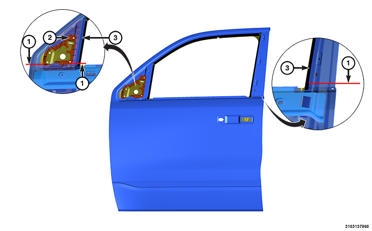 |
|||
|
|||
| CAUTION: |
Proper angles and depths must be maintained throughout the entire cut to prevent damage to surrounding components |
| NOTE: | Protect the composite reinforcement from excessive heat and weld spatter during the installation process. |
Overview: Depending on the type of door to be repaired, a full skin or a belt cut will be required. Belt cut replacement is necessary when a door with a full skin, around the window opening, has an angle that makes it to difficult to get tools into to do a quality hem flange installation. A butt-joint is used at this seam.
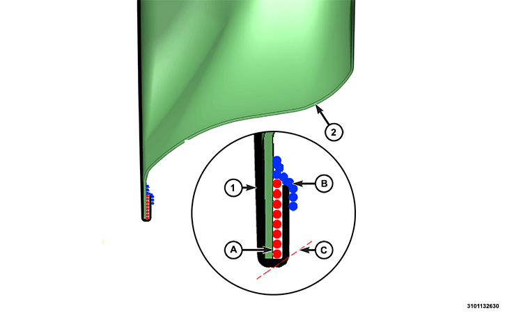
Preparation:
- Belt cut skins will require determining and cutting of the sectioning locations on the original panel and on the replacement panel.
- Remove the door skin by grinding the outer edge (C) until the hem flange is perforated.
- Cut around weld nuggets and spot welds with a spot weld cutting bit or similar weld removal tool, if necessary.
- If panel is attached with adhesive you may use heat, from a heat gun or inductor only, up to 204°C. (400F°). This will aid in loosening the bond.
- With an air chisel and a flat bladed bit, remove outer skin and any remaining hem flange.
- Grind any remaining weld nuggets flush with door frame, and remove all adhesive, paint, E-coating and corrosion protective coatings from the area where the structural adhesive will be applied, and where the 'butt-joint" is to take place. The metal should be completely bare and shiny in appearance, if the metal appears pewter in color all of the galvanized coating has not been removed.
- Straighten door flange and any remaining damage on door shell using the hammer and dolly method.
- The area of the new door skin that will make contact with the door shell will need to be scuffed with a course abrasive pad or ground with a 50 grit grinding disc. This will vary upon adhesive manufacturers, be certain to check adhesive manufacturer recommendations.
- Dry fit the new panel for margin and beltline alignment. Determine where to place clamps to hold the panel in place, as necessary.
CAUTION: Be certain the fit is good from the skin to door and door to door opening. Cured adhesive is extremely strong and will not allow for "adjustments".
- Without a mixing tip attached, purge a small amount of structural adhesive from the cartridge. This will ensure an even flow of both components.
- Attach a mixing tip and dispense a mixing tube's length of adhesive from the cartridge.
Installation:NOTE: Refer to the structural adhesives manufacturer for information on work, handling and curing times.
NOTE: Do not apply adhesive within 25 mm. (1 in.) of the belt cut location, if a belt cut was used.
- Apply a 10 - 13 mm. (3/8 - 1/2 in.) bead of structural adhesive to bare metal mating surfaces. Use a body filler applicator to level the adhesive, making sure to cover all bare metal to protect against corrosion.
NOTE: When applying adhesives be certain any and all drain holes remain open and clear of obstructions.
- Apply a second bead of adhesive to ensure proper bead thickness.
- Position the new panel. If repositioning is necessary slide the panel, do not lift or separate panels. Adjustments must be made by sliding, not lifting the panel(s). Apply clamps to hold panel in position, as necessary.
NOTE: There are many tools readily available to aid in the hem flange folding process.
- Roll the hem flange over. Remove excess adhesive. This will save time, as compared to waiting until cured.
- Re-check door gap and flushness to the vehicle opening and adjust as necessary.
- Allow the adhesive to cure per manufacturer recommendations. When fully cured, expect the adhesive to be a little tacky, as this is a normal characteristic of the adhesive. Remove clamps, if used.
- Remove any excess cured adhesive with a grinder or abrasive disc. All adhesive must be removed from the cosmetic repair area to ensure proper adhesion of repair and refinish materials.
- Weld the butt-joint with Gas Metal Arc Welding (GMAW), if a belt cut was used. Clean and dress welds accordingly.
- Apply fiber-reinforced waterproof body filler to the section seam, as necessary. When cured sand and apply conventional body filler and block sand.
- Apply an epoxy or anti-corrosion primer. When cured, lightly scuff.
- Seam seal the entire door. Duplicate the factory seam sealer. Apply a discrete bead around the rest of the door to seal and protect, maintaining the original appearance.
- Prime and paint per paint manufacturers recommendations.
NOTE: For cavity wax that meet FCA US LLC's approved replacement materials (Refer to 31 - Collision Information/Approved Materials/ADHESIVES SEALERS AND ADDITIONAL MATERIALS) .
- Apply inner panel cavity wax corrosion inhibiting materials.
Body Side Aperture
Overview: FCA US LLC's recommended repair procedure for body side aperture / quarter panel replacement include butt joints using backer panels with structural adhesive at the sectioning joint, or a welded backer panel with a welded butt joint using GMAW (Gas Metal Arc Welding). Resistance spot welding with structural adhesive, referred to as weld bonding, should be used at all pinch welds and may be used at the drain trough and tail panel areas as well. With the exception of the sectioning joint, the rule to follow is "Re-assemble as it was built from the OEM". For further information on Welding and Weld Bonding (Refer to 31 - Collision Information/Standard Procedures/WELDING AND WELD BONDING) . GMAW (plug or puddle) welds may be used in place of STRSW (Squeeze Type Resistance Spot Welding) only in areas that specifically use spot welds and in areas that access limitations will not allow STRSW. GMAW cannot be used in the weld bonding process. Never weld with GMAW within 25mm. (1in.) of any area where structural adhesive is used. The weld "heat zone" will destroy the properties of the adhesive.
Vehicle design will determine if the sectioning location is to be in the pillar or the roof line area. Reference the vehicle specific Body Repair Manual to verify if any specific locations or warnings apply to body side aperture sectioning locations.
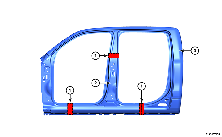 |
|||
|
|||
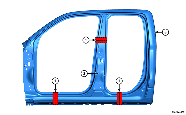 |
|||
|
|||
Preparation:
| NOTE: |
Be certain vehicle is evenly supported at normal suspension points. |
- Restore structural dimensions as well as all related mating flanges.
- Once sectioning locations have been established, cut original and replacement panels at the pre-determined locations. Remove spot welds within sectioned parameter.
NOTE: Be careful not to destroy any areas that may be able to be used as backer panels.
- If panel is attached with adhesive, you may use heat, from a non-flame heat source, up to 204°C. (400F°). This will aid in loosening the bond.
- Use an air chisel with a flat bladed bit to remove original panel.
- Using a hammer and dolly, restore any and all damage to mating surfaces.
- Create backer panels to be used at butt joints. Refer to Backer Panel Joint .
NOTE: It will be difficult to abrade the underside mating surface of the original panel, where backer panel is to be used, however this is important step and should be done effectively.
- Grind all mating surfaces with a 50 grit grinding disk. Remove all adhesive, sealers, paint, E-coating and corrosion protective coatings from the area where the structural adhesive and welds will be applied. The metal should be completely bare and shiny in appearance, if the metal appears pewter in color all of the galvanized coating has not been removed.
- Pre- drill any GMAW plug / puddle weld holes that may be necessary, with a 8mm. (5/16in.) hole.
- With the aid of an assistant, dry fit the panel. Apply clamps to hold panel in place, making note of locations. Install screws where accessibility prohibits the use of clamps. This will aid in proper alignment during installation.
- Without a mixing tip installed, purge a small amount of structural adhesive from the cartridge. This will ensure an even flow of both components.
- Attach a mixing tip and dispense a mixing tube's length of adhesive from the cartridge.
NOTE: Using scrap metal and adhesive, make test coupon samples and perform peel test to ensure your STRSW equipment is ready to apply welds as required. For further information For further information (Refer to 31 - Collision Information/Standard Procedures/WELDING AND WELD BONDING) .
Installation:NOTE: Refer to the structural adhesives manufacturer for information on work, handling and curing times.
- Install backer panels, refer to Backer Panel Joint .
- Apply 10 - 13mm. (3/8 - 1/2in.) bead of structural adhesive to the area where the two panels are to be bonded and weld bonded. Do not apply to areas that will only be STRSW or GMAW welded.
- Smooth the adhesive with a body filler spreader or equivalent, to cover all bare metal surfaces. Apply a second bead of adhesive to ensure proper adhesive thickness.
- With the aid of an assistant place the panel to the vehicle. If the panel needs to be adjusted, slide the panel.
NOTE: Adjustments must be made by sliding, not lifting the panel(s). Lifting will cause air bubbles and weaken the bond.
- Install clamps and screws to locations determined during the dry fit process.
- Remove all squeeze out of adhesive, prior to curing.
NOTE: Structural adhesive manufacturers will vary on time allowed for completion of STRSW in weld bond zones. Check and follow adhesive manufacturer recommendations.
- Apply STRSW to weld bond area immediately.
- Once fully cured, remove clamps and screws. When fully cured, expect adhesive to remain a little tacky, as this is a normal characteristic of the adhesive.
- Complete STRSW and / or GMAW (plug / puddle ) welds.
- Finish / Dress the welds as necessary. If screws were necessary bevel the screw holes. Prepare the joint and screw holes by grinding the area with 50 grit grinding disc. Get in seams as best as possible without thinning the metal.
- Remove any excess cured adhesive with a grinder or abrasive disc. All adhesive must be removed from the cosmetic repair area to ensure proper adhesion of repair and refinish materials.
- Apply fiber-reinforced waterproof body filler to screw holes and joint. Complete the repair using conventional body filler, and block sanding.
- Apply an epoxy or anti-corrosion primer. When cured, lightly scuff and then apply seam sealer as necessary.
- Prime and paint per paint manufacturer recommendations.
NOTE: For cavity wax that meet FCA US LLC's approved replacement materials (Refer to 31 - Collision Information/Approved Materials/ADHESIVES SEALERS AND ADDITIONAL MATERIALS) .
- Apply inner panel cavity wax corrosion inhibiting materials.
Metal Fatigue/Stress Crack
Overview: On rare occasions you may encounter metal fatigue, also referred to as stress cracks. This will appear as a crack starting at an edge and trailing away. Follow these steps for a proper repair:
- Locate the trailing end of the crack and drill a 3 mm. (1/8 in.) hole at the very point at which it stops. This is referred to as "Stop Drilling".
- Remove all contaminants and coatings including primer, paint and anti-corrosion, from the repair area. Surface should be clean and shiny (if pewter in color then anti-corrosion has not been removed).
- Identify the type of metal to be welded and the recommended welding process for that metal as found in Standardized Steel Identification (Refer to 31 - Collision Information/Technical Specifications/STANDARDIZED MATERIAL IDENTIFICATION) .
- Stitch weld the seam/crack closed using the recommended welding process and in accordance with the welding guidelines (Refer to 31 - Collision Information/Standard Procedures/WELDING AND WELD BONDING) .
- Dress the welds as necessary. Careful not to thin the base metal.
NOTE: For approved cavity wax (Refer to 31 - Collision Information/Approved Materials/ADHESIVES SEALERS AND ADDITIONAL MATERIALS) .
- Depending on the location and visibility of the repair surface refinishing will vary from body filler, finishing and painting to simply applying an epoxy or anticorrosion primer and rubberized undercoating.
- Apply inner panel cavity wax corrosion inhibiting materials.