Standard Procedure
Sectioning Locations And Procedures
▸Contents: 31 - Collision Information
Position Statements
- Authentic Mopar® Glass Replacement
- Reconditioned Wheel Usage
- Replacement Seat Covers And Seat Cover Repairs
- Salvaged Air Bags Or Other Salvaged Restraint System Component Usage
- SCAN TOOL SUPPORT BEFORE and AFTER COLLISION REPAIR
- Steering System
- Repair Parts Used For Structural Repairs
- Use Of Aftermarket Parts
- Use Of Heat While Repairing Damaged Structural And Non-Structural Components
- Use Of Optional Oe Parts
- Bumper/Fascia Repair With Adas
- One-Time-Use Parts & Fasteners
Standard Procedure
- Service After A Supplemental Restraint System Deployment
- Handling Non-Deployed Supplemental Restraints
- Post Collision Seat Belt Inspection
- Post Collision Scan Tool Inspection
- Recalibration Of Sensors And Modules
- Basecoat/Clearcoat Finish
- Finesse Sanding, Buffing, And Polishing
- Paint Touch-Up
- Rivet Nut Procedure
- Roof Panel Weld Stud
- Non-Structural Sheet Metal Repair
- Welding And Weld Bonding
- Sectioning Locations And Procedures
- Hoisting And Jacking
- Stationary Glass
- Corrosion Protection
Approved Materials
| WARNING: |
Sectioning of components may only be performed in the described areas if damage to component does not extend past sectioning location. Should damage extend past sectioning location entire component replacement is the only acceptable repair. |
USE OF HEAT DURING REPAIR- Be certain to follow guidance and instructions as found in the Use of Heat While Repairing Damaged Structural and Non-Structural Components (Refer to 31 - Collision Information/Position Statements/USE OF HEAT WHILE REPAIRING DAMAGED STRUCTURAL AND NON-STRUCTURAL COMPONENTS) .
| WARNING: |
Failure to follow these instructions may result in possible serious or fatal injury. |
| CAUTION: |
Service assemblies for body components may be disassembled if utilization of the subcomponents is more appropriate to the repair or to reduce vehicle disruption. The structural and non-structural metal on the RAM Pickup Truck (DT) may be sectioned in several areas providing the prescribed methods below are adhered to.
The joint should whenever possible be performed in as “flat” an area as possible to simplify the repair. While the joint may include “holes” and formations, it is suggested they be avoided but where this is not possible, the technician must ensure that the additional material thickness does not impede installation of fasteners, etc. that the hole exists for.
All dimensions are to be restored to factory specifications prior to full or partial component replacement.
| CAUTION: |
NVH foam should be removed from the weld area, as material may be flammable. |
| CAUTION: |
Do not apply any corrosion protection or NVH foam prior to completion of welding, as materials are flammable. |
The described sectioning locations only explain joint location and type. All other welds along the sectioned portion of the component must be replaced. Squeeze Type Resistance Spot Welding (STRSW) is the method to be used. If accessibility prevents application of spot welds, MIG plug welds are to be used. Welding of structural panels through 3 or more tiers of panel stack ups will require 9.5 mm. plug welds. Exterior panels should be installed using 8 mm. plug welds. For further information (Refer to Collision Information/Standard Procedures/WELDING AND WELD BONDING) .
| NOTE: |
For cavity wax that meet FCA US LLC's approved replacement materials (Refer to 31 - Collision Information/Approved Materials/ADHESIVES SEALERS AND ADDITIONAL MATERIALS) . |
When welding is completed apply inner panel rust proofing cavity wax. Apply to the inner cavity areas in two applications with a 30-minute flash period between the applications. Pay particular attention to areas which have been welded. Corrosion protection should always be restored to manufacturer specifications. For further information on Corrosion Protection (Refer to 31 - Collision Information/Standard Procedures/CORROSION PROTECTION) .
Finish, sealers, adhesives and silencers should be reapplied or replaced to OEM locations and specifications (Refer to 31 - Collision Information/Locations/STRUCTURAL ADHESIVE, FLEXIBLE ADHESIVES AND SEAM SEALER LOCATIONS) .
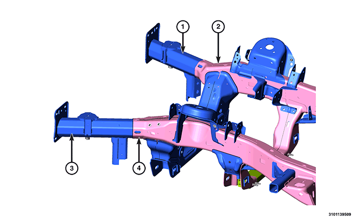
Front Frame Rail Replacement
 |
|
1 - Right Front Rail Extension |
|
2 - Right Front Frame Rail |
|
3 - Left Front Frame Rail Extension |
|
4 - Left Front Frame Rail |
- Before proceeding with this repair procedure review the required service warnings and precautions.
- Remove all parts needed to gain access to the repair area. (Refer to the appropriate Service Information - Removal Procedures).
- Mount the vehicle on an appropriate frame straightening equipment (frame rack).
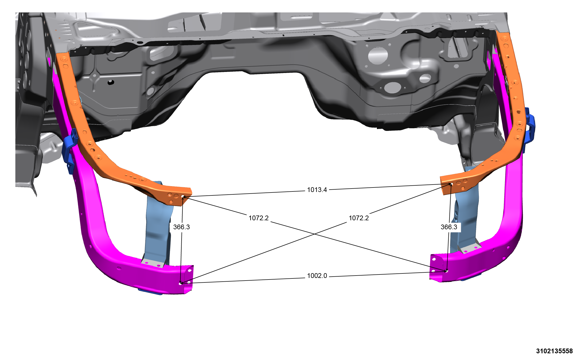
- Using a three-dimensional measuring system, measure and straighten the frame to the proper frame specifications (Refer to 31 - Collision Information/Technical Specifications/FRAME DIMENSIONS) .
CAUTION: Do not use an oxy-acetylene cutting torch to remove the damaged frame rail tip. This is due to the inaccurate nature of the cut-line and the fact that the high temperatures achieved during flame cutting will change the metal characteristics and may weaken the frame or repair location.
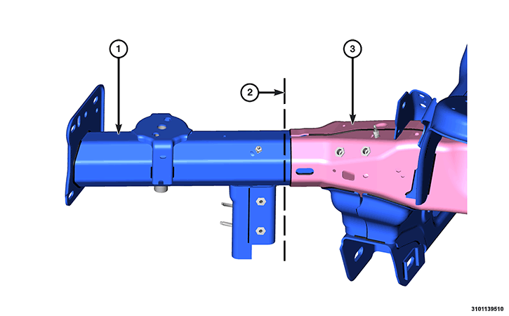
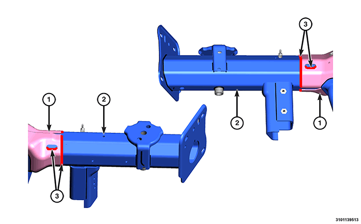
- With the use of a plasma cutter, reciprocating saw or equivalent, carefully cut the front rail extension (1) along the cut line (2), using care not to cut the frame rail (3) and surrounding components.
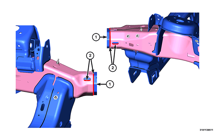
NOTE: Left side shown, right side similar. - With the use of an angle grinder, remove the remaining front rail extension (1) and weldments (2).
- Remove the remaining portion of the frame rail extension (1) from the frame rail.
- With the use of a grinder, remove the e-coat and galvanizing within 25 mm (1 in) of the weld zone on the outer and inner area of the front rail extension replacement part and front frame rail.
NOTE: The front rail extension consists of varying degrees of thickness from front to rear. Be certain to use the portion located closest to the frame rail to perform test welds and adjust the welder.
- Refer to the welding chart for proper wire and welder settings and use the original front rail extension to adjust the welder and be certain of a proper welding bead (Refer to 31 - Collision Information/Standard Procedures/WELDING AND WELD BONDING) .
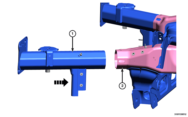
- Install the replacement front frame extension (1) into the front frame rail (2) and position using three-dimensional measuring equipment.
- When positioned correctly, apply tack-welds to secure the position.
- Complete the welds (3) using a skip-stitch method-
- Welding in a 51 mm (2 in) increment
- Allow the area to cool between welding operations
- Then welding the opposing side in a 51 mm (2 in) increment
- Repeat until the weld areas are completed on the front frame extension (1) and the front frame rail (2)
- If necessary, cosmetically dress the weld without removing any base metal.
- Clean the welded area of any burned coatings and weld spatter.
- Apply refinish materials to the exterior of the front rail extension and front frame rail to restore corrosion protection and appearance.
NOTE: When applying the rust proofing be certain to apply generously, to be certain the welded areas are fully covered.
- Apply a creeping wax type rust proofing material for corrosion protection to the inner cavity of the front rail extension and front frame rail.
Hydroform Fender Rail Repair
| CAUTION: |
This repair procedure assumes damage to the right or left hydroform fender rail. Prior to any repairs, the vehicle must be mounted on the appropriate frame repair equipment (“frame rack”), checked with three dimensional measuring equipment, and necessary pull corrections made. If damage exists in the hydroform fender rail, or cab beyond the area covered by this service procedure after dimensional corrections are made, the hydroform must be replaced in its entirety. |
| CAUTION: |
Inspect the tire winch assembly for damage. If any one or more of the following are evident, replace the winch assembly. |
- Before proceeding with this repair procedure review the required service warnings and precautions.
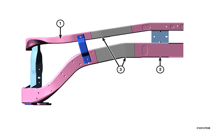
- Remove all parts needed to gain access to the repair area. (Refer to appropriate Service Information - Removal Procedures). HYDROFORM FENDER RAIL
1 - Upper Hydroform Fender Rail
2 - Lower Hydroform Fender Rail
3 - Sectioning Area
- Disconnect and isolate the battery negative cable(s) in accordance to the service information.
CAUTION: Do not use any flame or plasma cutting equipment to cut the frame in this procedure. The inaccurate and high temperatures achieved during flame or plasma cutting will change the metal characteristics and may weaken the frame or repair location.
- Using a reciprocating saw or equivalent, cut the fender rail and shotgun at a straight and square section of the hydroform and remove.
- Smooth and square the cut edges.
- Using the damaged structure as a reference cut the service part at the same location as the first cut. Smooth and square the cut edges.
NOTE: The repair structure should butt up to the remaining structure and provide the same overall vehicle geometry.
- Fabricate 51 mm (2.0 in) long repair inserts using scrap from the old structure or the replacement part. It will be necessary to split the inserts on each of their four sides to fit into the hydroform.
- Remove any paint or e-coat from the inserts and also to the interior and exterior of the hydroforms.
- Drill plug weld holes as described below.
- On the upper rail, drill one 13 mm (0.5 in) hole on each side of the rail, 13 mm (0.5 in) from the butt joint of the tubes.
- On the lower rail, drill one 13 mm (0.5 in) hole on the top and bottom sides of the rail 13 mm (0.5 in) from the butt joint of the tube.
- On the lower rail, drill two 13 mm (0.5 in) holes on the inner and outer sides of the rail 13 mm (0.5 in) from the butt joint of the tube.
CAUTION: Shield the surrounding area and components from exposure to the welding spatter and heat.
- Install the insert (25 mm (1 in) into the replacement part and tack into place with a weld.
- Insert the service part into place and using the appropriate measuring equipment, verify the front end sheet metal bracket's location in all three (X,Y, and Z) planes of space.
- Complete all 360° plug welds.
NOTE: Before the final welding, use three dimensional measuring equipment to ensure the part is in the correct location. Verify that tap plate extrusion at the bottom of the vertical post lines up with the isolator and hole in the frame perch mount. Also ensure the lower radiator closure tube is bolted into the forward shotgun ends.
- Complete welding by making a 360° butt weld around the fender rails.
- Metal finish the exposed welds on the hydroforms.
- Dress the welded area and apply corrosion resistant coatings inside and out.
- Inside the rail, inject a creeping wax based rust inhibitor compound to the inside of the hydroforms ensuring 100% coverage including the mating face between the fender rail sections and insert such that corrosion protection is restored in the internal cavity.
- Apply a durable top coat to the outside of the repair area.
- Complete the remainder of repairs.
- Install all the removed parts. (Refer to appropriate Service Information – Installation Procedures.)
- Connect and the battery negative cable(s) in accordance to the service information.
Body Side Aperture
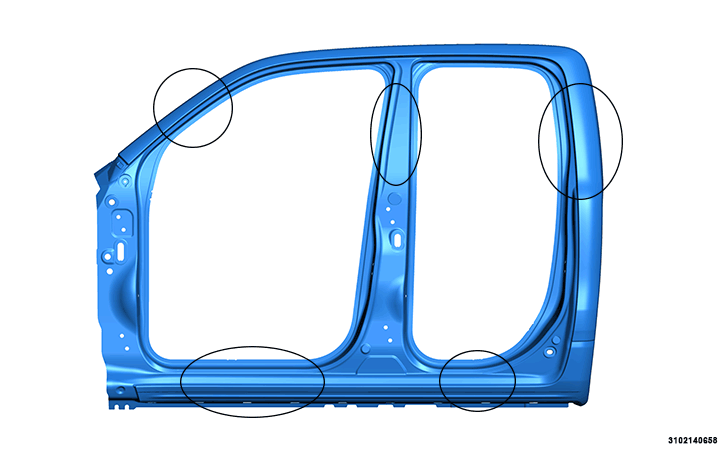
Crew Cab Outer Body Side Aperture
 |
Quad Cab Outer Body Side Aperture
 |
| NOTE: |
Left side shown, right side similar. |
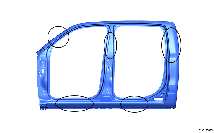
The outer body side aperture has many areas in which it may be sectioned in.
The outlined areas represent general sectioning areas and may be sectioned within.
| NOTE: | To prevent warping, apply 25 mm. (1 in.) stitch welds until the sectioning joint is completely welded. |
A Butt-joint with a 13 mm (0.5 in.) welded backer panel is to be used in all sectioning areas of the outer body side aperture.
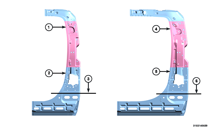
C-Pillar Inner Panel Sectioning
 |
||||||
|
||||||
| NOTE: |
Left side shown, right side similar. |
| NOTE: |
The shoulder belt reinforcement is integrated into the C-pillar inner panel. |
Sectioning in these areas will allow for partial replacement without disturbing unnecessary components.
When sectioning these areas a modified lap joint is to be used. Further information on modified lap joints can be found in the “Welding and Weld Bonding” section (Refer to 31 - Collision Information/Standard Procedures/WELDING ANS WELD BONDING) .
| NOTE: | To prevent warping, apply 25 mm (1 in) stitch welds until the sectioning joint is completely welded. |
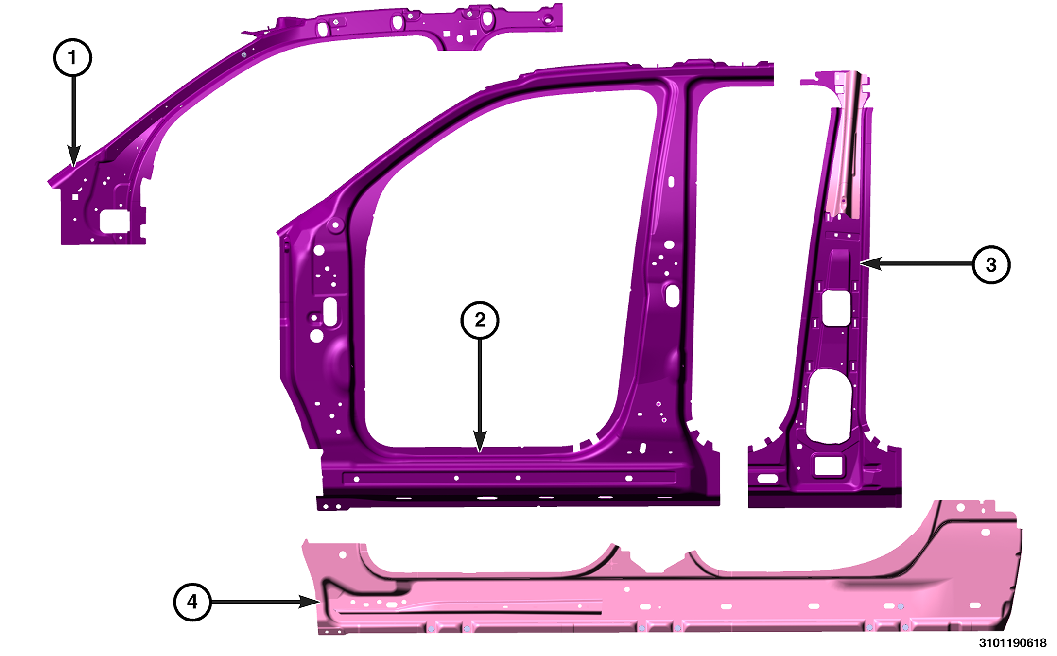
Inner Body Side Components - Do Not Section
 |
| NOTE: |
Left side shown, right side similar. |
|
BODY SIDE REINFORCEMENTS AND PANELS — DO NOT SECTION |
|---|
|
1- A-Pillar Reinforcement (1300 MPa) |
|
2- Inner Door Ring (Varies 550 MPa to 1300 MPa) |
|
3- B- Pillar Reinforcement (1300 MPa) |
|
4- Inner Sill Panel (690 MPa) |
Due to the usage of the type of metal and / or the tensile strength involved on the inner components and reinforcements sectioning of these parts are not allowed. Complete replacement of the component or reinforcement is the only acceptable repair.
It will be necessary to use a Tungsten Carbide Drill Bit to release the spot welds along the areas where these parts join other components.
Front Door Composite Reinforcement
| WARNING: |
Composite Reinforcements must be installed to maintain component strength standards. |
| WARNING: |
Failure to follow these directions may result in serious or fatal injury. |
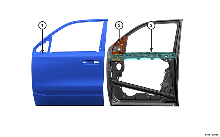 |
| NOTE: | Door outer belt reinforcement (3) transparent for clarity. |
|
1- Outer Door Panel (310 MPa) |
|
2- Front Door Composite Reinforcement |
|
3- Door Outer Belt Reinforcement (270 MPa) |
If the front door composite reinforcement (2) is damaged the front door must be replaced. The Composite Reinforcements absolutely must be in place .
B-Pillar Composite Reinforcements
| WARNING: |
Composite Reinforcements must be installed to maintain component strength standards. |
| WARNING: |
Failure to follow these directions may result in serious or fatal injury. |
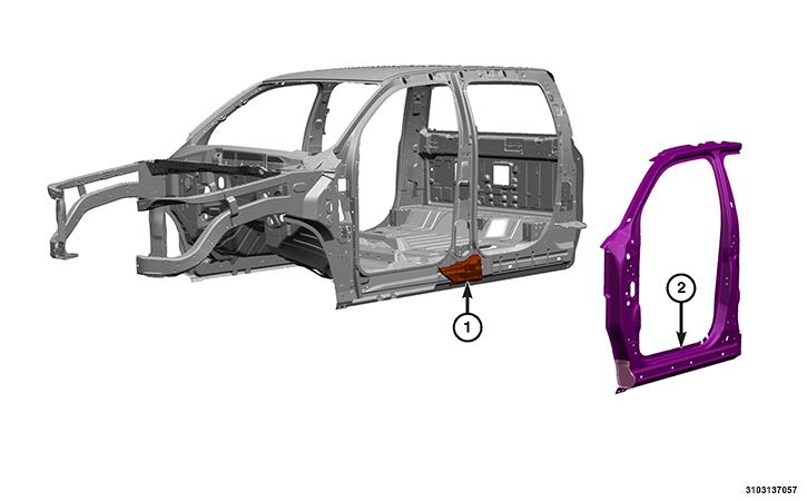
If the B-pillar composite reinforcement or any component that makes contact with the composite reinforcement is replaced it will need to be re-secured. Composite Reinforcements absolutely must be reinstalled .
 |
|
1- B-Pillar Composite Reinforcement |
|
2- Inner Door Ring (Varies 550 MPa to 1300 MPa) |
Replace the new or the re-used undamaged B-pillar composite reinforcement with structural adhesive during the repair process. For structural adhesives that meet FCA US LLC's approved replacement materials (Refer to 31 - Collision Information/Approved Materials/ADHESIVES SEALERS AND ADDITIONAL MATERIALS) .
When mounting the composite reinforcement align the alignment tabs with the corresponding holes in mating components.
Front Seat Crossmember Composite Reinforcements
| WARNING: |
Composite Reinforcements must be installed to maintain component strength standards. |
| WARNING: |
Failure to follow these directions may result in serious or fatal injury. |
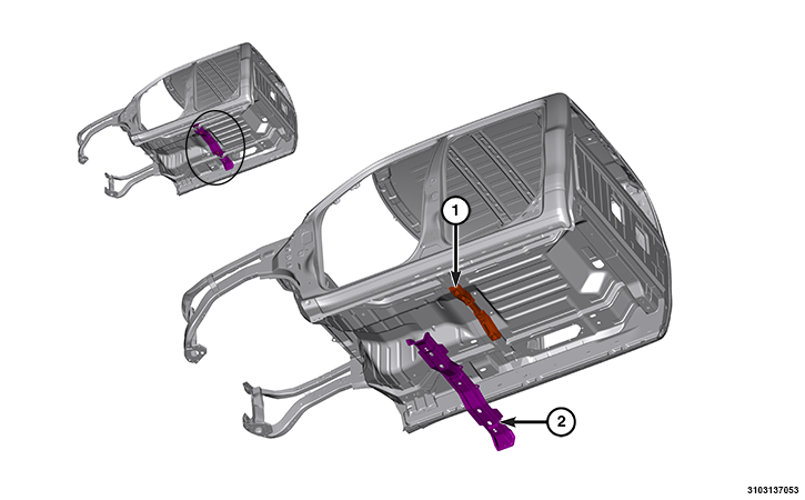
If the front seat crossmember composite reinforcement or any component that makes contact with the composite reinforcement is replaced it will need to be re-secured. Composite Reinforcements absolutely must be reinstalled .
 |
|
1- Front Seat Crossmember Composite Reinforcement |
|
2- Front Seat Crossmember (1300 MPa) |
Replace the new or the re-used undamaged front seat crossmember composite reinforcement with structural adhesive during the repair process. For structural adhesives that meet FCA US LLC's approved replacement materials (Refer to 31 - Collision Information/Approved Materials/ADHESIVES SEALERS AND ADDITIONAL MATERIALS) .
When mounting the composite reinforcement align the alignment tabs with the corresponding holes in mating components.