Standard Procedure
Welding And Weld Bonding
▸Contents: 31 - Collision Information
Position Statements
- Authentic Mopar® Glass Replacement
- Reconditioned Wheel Usage
- Replacement Seat Covers And Seat Cover Repairs
- Salvaged Air Bags Or Other Salvaged Restraint System Component Usage
- SCAN TOOL SUPPORT BEFORE and AFTER COLLISION REPAIR
- Steering System
- Repair Parts Used For Structural Repairs
- Use Of Aftermarket Parts
- Use Of Heat While Repairing Damaged Structural And Non-Structural Components
- Use Of Optional Oe Parts
- Bumper/Fascia Repair With Adas
- One-Time-Use Parts & Fasteners
Standard Procedure
- Service After A Supplemental Restraint System Deployment
- Handling Non-Deployed Supplemental Restraints
- Post Collision Seat Belt Inspection
- Post Collision Scan Tool Inspection
- Recalibration Of Sensors And Modules
- Basecoat/Clearcoat Finish
- Finesse Sanding, Buffing, And Polishing
- Paint Touch-Up
- Rivet Nut Procedure
- Roof Panel Weld Stud
- Non-Structural Sheet Metal Repair
- Welding And Weld Bonding
- Sectioning Locations And Procedures
- Hoisting And Jacking
- Stationary Glass
- Corrosion Protection
Approved Materials
Safety Notice
| CAUTION: |
All Service and rebuilding instructions contained herein are applicable to, and for the convenience of, the automotive repair industry only |
The service procedures recommended and described in this publication were developed for professional service personnel, and are effective methods for performing vehicle repair.
It is important to note this publication contains various Cautions and Warnings . These should be read carefully in order to minimize risk of personal injury or the possibility that improper service may damage the vehicle or render it unsafe. FCA US LLC cannot possibly know, evaluate and advise the service trade of all conceivable ways in which service may be performed, or the possible hazards of each. Consequently, FCA US LLC has not undertaken any broad service review. Accordingly, anyone that uses a service procedure or tool that is not recommended in this publication must be certain that neither personal safety, nor vehicle safety will be jeopardized by the service methods they select.
Safety Precautions
| WARNING: |
Failure to follow these instructions may result in possible serious or fatal injury. |
Welding
- Comply with all federal, state and local regulations to avoid any injuries due to shock, fires, fumes, sparks and liquids.
- All flammable materials or liquid should be stored in tightly sealed and labeled containers, and used only in well ventilated areas.
- No spark producing equipment should be permitted in any area where flammable materials are being handled or stored.
Adhesives:
- Safety Data Sheets (SDS) must be available and understood before adhesives are handled.
- All personnel should be instructed on the proper procedures to prevent skin contact with solvents, curing agents, and uncured base adhesives, which could cause allergic reactions or sensitization.
Introduction
The purpose of this document is to clearly explain the welding options available to the collision repair technician and how to determine that welding repairs are made properly. The primary types of welding covered in this section are Squeeze Type Resistant Spot Welding (STRSW), Gas Metal Arc Welding (GMAW), Metal Inert Gas (MIG) Brazing and Weld Bonding (a combination of STRSW and structural adhesive). Proper training and weld testing are required to ensure that a safe, high quality, vehicle repair is made.
|
INDEX |
REFERENCE |
|---|---|
|
Panel Removal |
Panel Removal |
|
Key Points of a Welding Repair |
Key Points of a Welding Repair |
|
Requirements of a Welding Repair |
Requirements of a Welding Repair |
|
Modified Lap Joint |
Modified Lap Joint |
|
Types of Welding (STRSW, GMAW and Weld Bonding) |
Types of Welding |
|
Weld Processes (STRSW, GMAW and Weld Bonding) |
Weld Processes |
|
Minimum Weld Nugget Requirement Chart |
Minimum Weld Nugget Requirement Chart |
|
Training and Qualification |
Training and Qualification |
Panel Removal
| WARNING: |
Always Wear Safety Goggles, Work Gloves, Hearing Protection and a Dust Mask when removing welded panels this way. Failure to follow these instructions could result in serious or fatal injury. |
When removing panels and components for replacement, care must be taken not to damage the underlying component. On welded and "Weld Bonded" panels spot welds must be removed using a spot weld cutting type tool, or equivalent. On panels that are adhesive bonded or weld bonded it is acceptable to use heat up to 204°C. (400°F.) , from a Non-Open Flame heat source such as a heat gun. This will loosen the bond, so less damage is inflicted to the mating surface. After panel is removed, any remaining weld nugget should be ground smooth. Cut-off wheels should not be used, as there is potential to remove material from the base material which would weaken the final repair. Place an air hammer with a flat bladed chisel bit (or equivalent) in between panels and remove the panel. Care should be taken as to not damage mating flanges and the surrounding components.
Key Points of a Welding Repair
- Poor fit up will adversely affect weld quality and may result in a weld failure due to excessive metal stretching around the nugget.
- Clamps/Clecos should be used to bring parts together and hold them in position.
- Clamps/Clecos should be insulated when using STRSW to control weld current shunting (This can be accomplished with specialized clamps or by placing a insulating material such as cardboard between the clamp jaws and the panels.)
- Number, size and location of welds should closely duplicate the original assembly. Do not place the new spot weld directly on the original spot weld location. Placement of a new weld over an original weld location may lead to metal fatigue or poor weld quality.
- Surface of the steel parts should be clean and free of scale, rust, paint, cured adhesives/sealers and any other contaminants that could adversely affect the quality of the weld joint. This includes the removal of any E-coat applied to the service part within 25 mm. (1 in.) of any welds.
- Proper corrosion protection must be installed when repairs are complete (Refer to 31 - Collision Information/Standard Procedures/CORROSION PROTECTION) .
- If the joint originally had adhesive, all E-coat must be removed where the adhesive is to be reapplied.
- Weld-through zinc rich primer/coating is recommended for use to protect adjacent areas to the weld from corrosion. When using weld-through zinc coatings while utilizing GMAW (MAG Welding), the coating must be removed completely from the weld zone before welding to reduce the possibility of porosity in the weld.
- Do not remove base material from the base panel when releasing welds.
| NOTE: |
FCA US LLC recommends the same quantity of welds as the original panel, but placement of the new weld should NOT be put directly on the original spot weld location. Placement of a new weld over an original weld location may lead to metal fatigue or poor weld quality. |
Requirements of a Welding Repair
The number one requirement of any welding repair is to restore the vehicle to its OEM condition. Materials and technologies should duplicate original OEM conditions as much as possible. To meet this requirement, the technician must ensure the following:
- Panel layering (shingling) is the same as original
- Part fit up is correct
- Equivalent sealers and/or adhesives are utilized
- Welds are replaced in the same size, quantity and location
- Weld-through primers are recommended
- Structural adhesives and sealers must be replaced where they were located
A significant amount of structural adhesive is used at the OEM to improve joint strength. It may be difficult to determine if the material between the panels is an adhesive or a sealer, and for this reason, the following guideline should be used: If in doubt, use a two-component, corrosion inhibiting, structural adhesive. GMAW welding is not recommended within 25 mm. (1 in.) of the adhesive as it creates heat that will destroy the adhesive. STRSW on the other hand, can weld through the adhesive and will not destroy its properties.
| NOTE: |
For recommended weld-through primer, impact resistance grade and sheet metal bonding grade structural adhesives that meet strength and corrosion protection qualities (Refer to 31 - Collision Information/Approved Materials/ADHESIVES SEALERS AND ADDITIONAL MATERIALS) . |
Modified Lap Joint
| NOTE: |
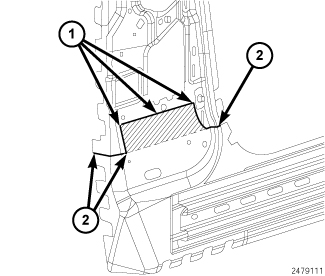
Parts shown for example purposes only. Emphasis is on joint design and proper plug weld placement. |
 |
|
|
|
1 - LAP-JOINT WELDS |
|
2 - BUTT-JOINT WELDS |
The repair joint is a combination lap-joint (1) and butt-joints (2) – the panels are lapped in the flat areas and butted in contoured locations and at weld flanges. The graphic better illustrates this process.
 |
||
|
||
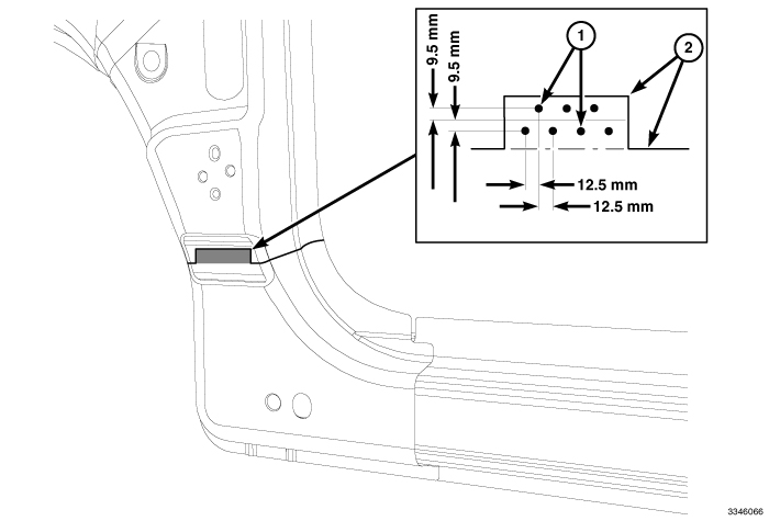
The MIG plug welds, or "puddle welds" should be made after drilling 8 mm (5/16 in) holes and should be staggered 12.5 mm (0.5 in) apart following the centerline of the lap and should be alternating above and below the centerline 9.5 mm (3/8 in.).
In the lap-jointed area, staggered MIG plug welds (1) are used to augment the joint and all edges of the lapped panel seam (2) should be completely welded.
Types of Welding
Squeeze Type Resistant Spot Welding (STRSW)
- STRSW relies on the resistance of the material being welded to create heat as a current is passed through. The materials being welded are squeezed together, and as current passes through, resistance causes heat buildup. The force of the tips and the heat from the current allow the materials to fuse together. The current is removed and the force from the welding tips is held during a cool down cycle. When the cool down cycle is complete, the pressure is released and the next weld is positioned.
- Learning how to create weld coupons, refer to Test Weld Coupon and then performing a destructive test using these coupons, is the key to successfully using STRSW. FCA US LLC requires a physical test using test coupons and the methods outlined in this document to test welds prior to making repairs.
- Tip condition is very important for producing proper welds. Inspect tips often and either dress or change per equipment manufacturer recommendations.
- High-quality welding equipment must be used or welds may be inadequate. Also, the equipment must be able to produce repeatable welds from the beginning of the repair to the end.
Gas Metal Arc Welding (GMAW) or "MIG"
- GMAW is an arc welding process where the electrode wire is fed through a weld gun and is surrounded by a shielding gas. The term MIG comes from early uses on aluminum where argon was used as shielding gas and the process was referred to as Metal Inert Gas welding. The GMAW process is currently the most common in the uni-body repair environment.
Flux Core Arc Welding (FCAW)
- FCAW is an arc welding process where electrode wire is fed through a weld gun and is not surrounded by a shielding gas.
- The welding zone is protected by the use of flux that is located in the center of electrode wire.
- The surface of the completed will have slag left behind from the flux that will need to be removed prior to any refinishing process.
Metal Inert Gas (MIG) Brazing
- MIG brazing, is a brazing process where the electrode wire is fed through a weld gun and is surrounded by argon as shielding gas.
- The application of the process is similar to GMAW. However, it utilizes a different electrode and shielding gas and does not melt the base material.
- Due to the lower melting point of the electrode, it produces a much smaller heat affected zone than GMAW.
Weld Bonding
- A method of joining metals using STRSW in conjunction/combination with a structural adhesive.
- Weld bonding provides the customer with a superior repair as compared to the traditional plug/puddle welding process using GMAW. Structural adhesive should not be used in a joint that did not originally contain it.
- The repair joint or seam should duplicate the OE build as closely as possible, unless otherwise stated in the collision information.
| NOTE: |
FCA US LLC DOES NOT approve or endorse the use of structural adhesives alone in the replacement of body panels. |
Weld Processes
Squeeze Type Resistance Spot Welding (STRSW)
Applications
- With advancements in equipment technologies, such as computer program controlled and inverters, STRSW is not restricted to light gauge sheet metal any longer. Heavier gauges of high strength and coated steel, currently used in vehicle structures, can now be welded in the field, providing destructive testing is performed on each combination. This is to ensure quality welds are being maintained.
Equipment Requirements
- Equipment must produce two sided welds
- Equipment must have been tested to SAE J2667 with satisfactory results obtained
- Equipment must have the capability to create welds that comply with the Minimum Weld Nugget Requirement Chart
- Technician must have the appropriate sheet metal measuring equipment to ensure their welds meet the minimum weld nugget size for the actual panels being welded
Gas Metal Arc Welding (GMAW) or "MIG"
Applications
- Sheet metal repairs where STRSW is not available or practical, and truck frame repairs.
- The most common usage of GMAW on uncoated or galvanneal coated steel will utilize a 75% Argon - 25% CO2 shielding gas mix, and AWS specification ER70S6 wire. When welding galvanized material, Flux Core Arc Welding (FCAW) using AWS specification E71T-GS wire should be used to avoid weld porosity from the zinc in the galvanizing.
Weld Process
|
COMPONENT PARTS |
TRUCK FRAME |
BODYSHELL EXTERIOR & UNDERBODY PANELS |
||||
|---|---|---|---|---|---|---|
|
Zinc and Zinc Iron Alloy coated sheet steels |
||||||
|
WELDING PROCESS |
GAS METAL ARC (Note: 1) |
FLUX CORED ARC |
GAS METAL ARC (Note: 1) |
MIG BRAZE (Note: 2) |
GAS METAL ARC (Note: 1) |
FLUX CORED ARC |
|
Material Type |
High Strength and Structural Quality Steels which includes HSLA, Martensitic, and Dual Phase materials |
|||||
|
Material Thickness Range |
2 mm - 4 mm |
0.6 mm - 1.02 mm |
>1.02 mm - 3.0 mm |
|||
|
ELECTRODE TYPE (AWS SPEC. A5.18) |
AWS CLASS. ER70S-6 |
AWS CLASS. E71T-11 |
AWS CLASS. ER70S-6 |
AWS CLASS. ERCuAl-A2 |
AWS CLASS. ER70S-6 |
AWS CLASS. E71T-11 |
|
ELECTRODE SIZE |
0.035 |
0.045 |
0.023 - 0.025 |
0.035 |
0.035 |
0.045 |
|
ELECTRODE MAKER |
Lincoln® |
Lincoln® NR-211-MP |
Lincoln® |
Lincoln® |
Lincoln® NR-211-MP |
|
|
WIRE FEED SPEED (in/min) |
245-250 Vertical Down |
110 Vertical Down |
95-115 All Welds |
150-155 Flat & Horizontal |
245-250 Vertical Down |
110 Vertical Down |
|
70-90 Flat & Horizontal |
70-90 Flat & Horizontal |
70-90 Flat & Horizontal |
70-90 Flat & Horizontal |
|||
|
TRAVEL SPEED (in/min) |
10 |
|||||
|
VOLTAGE |
19-20 |
15-18 |
16-19 |
18-19 |
19-20 |
15-18 |
|
POLARITY |
DCEP |
DCEN |
DCEP |
DCEP |
DCEP |
DCEN |
|
GAS FLOW (cfh) |
25-35 |
N/A |
25-35 |
25-35 |
25-35 |
N/A |
|
ELECTRICAL STICKOUT (in) |
1/2 - 5/8 |
3/8 - 1/2 |
1/2 - 5/8 |
5/8 - 3/4 |
1/2- 5/8 |
3/8 - 1/2 |
|
GAS TYPE |
75% Ar |
N/A |
75% Ar |
100% Ar |
75% Ar |
N/A |
|
25% CO2 |
25% CO2 |
25% CO2 |
||||
|
TYPE OF ARC TRANSFER |
Short Circuit |
Short Circuit |
Pulse |
Short Circuit |
||
These Procedure Specifications are appropriate as of this publication. Procedures may be superseded with new spec's at a later date.
Always process to the Thinner Material Thickness (TMT)
All persons performing welding must be qualified to weld in all positions.
| NOTE: |
Equipment Requirements
- The preferred GMAW welder will be a 220V. unit with minimum output capacity of 150 amps (250 amps suggested to avoid equipment limitations).
Limitations
- Welds must be "dressed", or ground down before applying topcoats.
- GMAW cannot weld through paints, sealers, or adhesives. Additionally, the zinc used in coated steels can lead to reduced weld strength due to porosity. This porosity problem on materials with heavy coatings can be dealt with by using FCAW.
- Due to the heat affected zone, structural adhesives cannot be applied within 25mm. (1in.) of GMAW welds.
Testing
- Weld coupons identical to the repair situation need to be created to help set up the welding equipment and weld process. These coupons then should be destructively tested to ensure proper quality welds are being made.
Post Weld Procedures
- When welding has been completed, welds in cosmetic locations must be dressed.
- Welds will need to be smoothed down to the height of the surrounding panel without any thinning of the sheet metal. This can be accomplished using one of many sanding or grinding products available in the aftermarket.
- Slag must always be removed prior to refinishing to restore corrosion protection and appearance.
- Corrosion inhibiting materials must be applied to seal the weld zone from future corrosion.
Metal Inert Gas (MIG) Brazing
Applications
- Is the recommended method for attaching steel that is greater than 600 MPa when accessibility to perform STRSW or weld bonding is not possible.
- It has a reduced heat affected zone as compared to GMAW.
- The lower heat involved will not affect the strength properties of the metal being welded
Flux Core Arc Welding (FCAW)
Applications
- Thicker gauge coated steels where the thickness of the metal is between 1.02 mm and 4 mm and tensile strength is below 600 MPa, such as truck frames.
- This type of welding is recommended for galvanized or zinc coated steels, due to porosity issues caused when welding with GMAW.
- AWS specification E71T-GS wire is recommended.
Minimum Weld Nugget Requirement Chart
|
*Governing Metal Thickness (GMT) |
**Minimum Weld Nugget Diameter |
|---|---|
|
0.64 mm. - 0.79 mm. |
3.5 mm. |
|
0.8 mm. - 0.99 mm. |
4.0 mm. |
|
1.0 mm. - 1.29 mm. |
4.5 mm. |
|
1.3 mm. - 1.59 mm. |
5.0 mm. |
|
1.6 mm. - 1.89 mm. |
5.5 mm. |
|
1.9 mm. - 2.29 mm. |
6.0 mm. |
|
2.3 mm. - 2.69 mm. |
6.5 mm. |
|
2.7 mm. - 3.04 mm. |
7.0 mm. |
*Governing Metal Thickness (GMT) = The minimum weld nugget for two thickness welds shall be based on the thinner of the two sheets being welded. The minimum weld nugget diameter for three thickness welds shall be based on the middle gauge of the three panels being welded (not necessarily the middle panel).
**Minimum nugget diameter should be measured with a vernier caliper. If the weld is not round, measure the major and minor diameter and average.
Equipment Limitations
- Each brand/model is limited to material capacity that can be welded.
- The facility power supply will impact equipment performance.
Access Limitations
- Due to the existing structure of the vehicle being repaired, each weld must be evaluated for feasibility. Due to power limitations of the equipment, tongs that are long and deep enough for certain welds may not be available, and the weld will need to be made by another method.
| CAUTION: |
All NVH foam must be removed from the repair area of the vehicle, as material is flammable. |
Preparation
- Prior to making repairs with STRSW, weld coupons must be created for testing. The test joint must be an exact duplicate of the original joint, including layering and adhesive application. The testing is required to ensure the repair restores the vehicle to its originally produced condition using the minimum weld nugget requirement chart.
- To correctly identify the material being welded or tested, the technician must posses an accurate material thickness gauge.
- No "improvements" to the vehicle design are allowed as this could have a negative impact on the vehicle as a whole. The repair should mirror what was used on the vehicle at the assembly plant.
- Note, the weld is affected by more than just the thickness or number of panels being welded, but also material coatings. Zinc based anti-corrosion coatings (i.e., galvannealing, galvanizing), sealers, adhesives, and E-coat will affect welder performance.
- When preparing an E-coated panel for STRSW the E-coat must be removed from both of the mating flanges within 25 mm. (1 in.) of any flange. Corrosion protection is required anytime you remove E-coat. A scuffing disc should be used to remove the E-coat without damaging other sheet metal coatings
- With advancements in technology some STRSW welders now have computer controlled programs. These technologically advanced welders are capable of measuring the thickness and resistance of the panels being welded including multiple tiers and types of metal. The computer program is able to process the information to provide the proper spot weld consistently.
- If the panel originally had structural adhesives it should be reapplied prior to welding. The adhesive should have a corrosion inhibitor and cover all bare metal.
- Prior to creating weld coupons and the final body repairs, all coatings and dirt/road debris must be removed.
Testing
- Weld coupons identical to the repair situation need to be made prior to performing any repair. These coupons must be tested (peel test) to determine if the weld nugget meets the minimum size outlined above in the Minimum Weld Nugget Requirement Chart. Keep in mind that different material coatings, coating thickness, material thickness, and joint configurations have a direct impact on nugget size.
Weld Bonding
| NOTE: |
Structural adhesive manufacturers will vary on time allowed for completion of STRSW in weld bond zones. Check and follow adhesive manufacturer recommendations. |
Application
- Weld bonding is the STRSW welding process utilizing structural adhesive between the panels that are resistance welded together. The adhesive creates a very stiff structure, while the welding eliminates concerns of the adhesives' peel strength.
- Additionally, the adhesive acts as a sealer and provides a high level of corrosion protection.
Sealers and Adhesives
- Sealers are materials placed on top of a seam to control water and air intrusion.
- Adhesives, providing structural improvements, are found between panels welded together. Adhesives also provide the qualities of sealers when applied correctly.
- The FCA US LLC recommendation is to replace any suspected adhesive with a two-component, corrosion inhibiting structural adhesive when any repairs are made, providing the STRSW process is applicable.
Test Weld Coupon
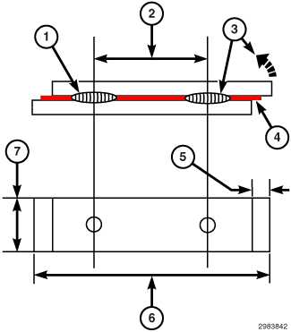
| NOTE: |
Periodically check the electrodes tips to determine wether the faces have been contaminated, damaged or increased in size. If any of these conditions have occurred, replace or re-face the electrode tips per equipment manufacturer recommendations. |
Weld Examples
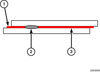 |
|
|
|
1 - STRUCTURAL ADHESIVE |
|
2 - WELD TOO SMALL |
|
3 - WELD NON-EXISTENT |
Current Level Low for Both Welds
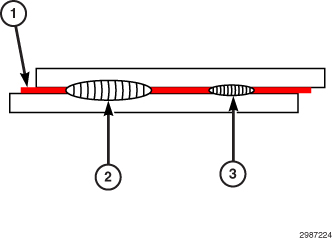 |
|
|
|
1 - STRUCTURAL ADHESIVE |
|
2 - WELD CORRECT SIZE |
|
3 - WELD TOO SMALL |
Current Level Medium for Both Welds
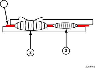 |
|
|
|
1 - STRUCTURAL ADHESIVE |
|
2 - WELD HAS HEAVY EXPULSION OF METAL AND SURFACE MARKINGS |
|
3 - WELD CORRECT SIZE |
Current Level High for Both Welds
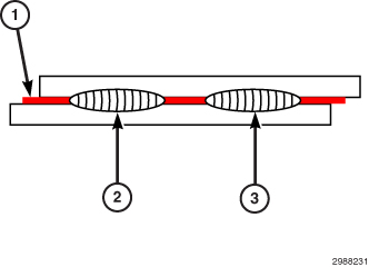 |
|
|
|
1 - STRUCTURAL ADHESIVE |
|
2 - WELD CORRECT SIZE |
|
3 - WELD CORRECT SIZE |
Current Level Adjusted to Provide Acceptable Welds
- Select the proper spot welding tong/arm which provides the best access to the areas of the vehicles where the spot welds are to be made.
- Obtain metal of the same thickness and coating (i.e., bare, galvanneal, or galvanized) to be welded. This metal will be used for spot welder set up. Damaged sheet metal taken from the vehicle being repaired may be used if it is from the area from which the work is to take place. The sheet metal must be flat, free of cracks, wrinkles and scored metal.
- Using the procedure outlined in Test Weld Coupon , prepare the test coupons.
- Clean and prepare both mating coupons. If using adhesives, verify the recommendations of the adhesive manufacturer. All contaminates such as rust scale, dirt, paint, and existing sealers and adhesives must be removed. Remove any E-coat within 25 mm. (1 in.) of where the welds are to be placed.
- If the panel joint originally contained structural adhesive, it should be applied to the coupon at this time.
- Install the equipment manufacturers recommended electrode tips.
- Adjust the welding electrode tip force, and clamp time per manufacturer recommendations.
NOTE: Galvanneal and galvanized coated steel will require more force
- As shown in Test Weld Coupon , place first weld at a position at least 12.5 mm. (0.5 in.) away from end weld coupons. Then make the second weld. The weld spacing should be the same distance as the original welds or the closest existing weld, whichever is the least on the vehicle being repaired.
- Destructively test the second weld to determine the size of the resistance spot weld produced (see examples in Test Weld Coupon . If the weld is insufficient, adjust the welder per the welder manufacturer recommendations and repeat steps 7, 8 and 9 until the proper weld size is achieved.
| NOTE: |
If the first weld becomes too "hot" before the second weld reaches the correct size, reduce the current settings for the first weld and continue increasing the current setting for the second weld until the proper size for the second has been reached. |
Final Weld Preparation
| CAUTION: |
All NVH foam must be removed from the repair area of the vehicle, as material is flammable. |
- Visually verify that mating flanges are free of scale, rust, dirt, paint and cured adhesives/sealers, as well as wrinkles. If cracked, wrinkled or scored metal exists the condition needs to be corrected at this time.
- E-coat within 25 mm. (1 in.) needs to be removed for STRSW. If Weld Bonding, E-coat should be ground off completely along seam.
NOTE: Corrosion resistance coating (i.e., galvanneal, galvanized) should not be removed during cleanup of components.
- Verify that the welder control settings are the same required to produce the second weld on the test coupons.
- If adhesive is to be used, apply it at this time. Clamp the component to the vehicle.
NOTE: Insulated clamps should be used, as not to shunt the weld current.
NOTE: During the welding of the component it will be necessary to visually verify that the weld being made is not placed directly over an existing weld. - Perform the welds on the vehicle.
NOTE: Structural adhesive manufacturers will vary on time allowed for completion of weld bond zones. Check and follow adhesive manufacturer recommendations.
- If adhesive was used, clean up any excessive squeezeout prior to adhesive curing.
Training and Qualification
Training
As with any equipment, proper training is required, and in the case of welding equipment this is no exception. The goal of automobile facilities and technicians is to restore the vehicle to its OEM condition.
Training must be considered a two-fold process:
- The technician must be well versed in how the equipment operates, how adjustments are made and what effects those adjustments have on the weld. The technician must also clearly understand the maintenance of the equipment and the impact of poor maintenance on welds and equipment longevity.
- The second and most important, aspect of the training, is weld quality confirmation. Destructive testing of weld coupons must be performed to ensure the minimum weld size is created. Physical appearance of the weld is not enough to determine the quality of the weld. Additionally, poor welds may also reduce the durability, or quality , of the repaired vehicle in time.
It is required that technicians have received training regardless of the welding equipment or method they utilize. Both training in the specific field of welding, and the particular equipment, are necessary to ensure safe, durable, quality welds are obtained.
Qualification
To demonstrate welding skill, it is highly important that technicians obtain certification from an organization such as the American Welding Society (AWS) or a certificate from the Inter-Industry Conference on Auto Collision Repair (ICAR).