Removal and Installation
Stabilizer Bar Link
▸Contents: 02 - Front Suspension
- Special Tools
Air Suspension
- Warning
- Description and OperationAir Suspension
- Diagnosis And Testing
Standard Procedure
- Technical SpecificationsTorque Specifications
Air Line
COMPRESSOR ASSEMBLY, Air Suspension
HOSE ASSEMBLY, Air Suspension
RESERVOIR, Air Suspension
SENSOR, Height
Removal and Installation
Front, Independent Front Suspension
- Description and OperationFront Suspension
Diagnosis and Testing
- Technical SpecificationsTorque Specifications
ARM, Lower Control
Removal and Installation
ARM, Upper Control
Removal and Installation
BALL JOINT, Suspension, Lower
BALL JOINT, Suspension, Upper
KNUCKLE, Steering
LINK, Stabilizer Bar
Removal and Installation
SHOCK ABSORBER, Suspension
Removal and Installation
SPRING, Front
Removal and Installation
STABILIZER BAR, Front
Wheel Alignment
REMOVAL
- Raise and support the vehicle (Refer to 04 - Vehicle Quick Reference/Hoisting/Standard Procedure) .
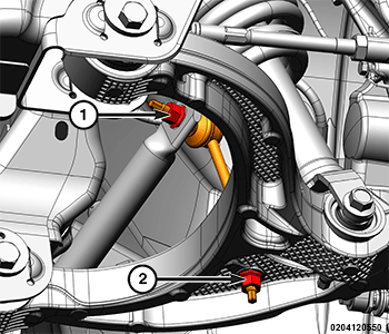
- Remove the stabilizer bar link lower nut.
1 - Stabilizer Bar Link Upper Nut 2 - Stabilizer Bar Link Lower Nut - Remove and DISCARD the stabilizer bar link upper nut.
- Remove the stabilizer bar link.
INSTALLATION
Follow the removal procedure in reverse for general reassembly of the components on the vehicle. The steps listed below are calling out specific procedures that should be followed during installation.
- Install a NEW stabilizer bar link upper nut and tighten to the proper (Torque Specifications) .
- Install the stabilizer bar link lower nut and tighten to the proper (Torque Specifications) .