Standard Procedure
Manual Reservoir Deflate
▸Contents: 02 - Front Suspension
- Special Tools
Air Suspension
- Warning
- Description and OperationAir Suspension
- Diagnosis And Testing
Standard Procedure
- Technical SpecificationsTorque Specifications
Air Line
COMPRESSOR ASSEMBLY, Air Suspension
HOSE ASSEMBLY, Air Suspension
RESERVOIR, Air Suspension
SENSOR, Height
Removal and Installation
Front, Independent Front Suspension
- Description and OperationFront Suspension
Diagnosis and Testing
- Technical SpecificationsTorque Specifications
ARM, Lower Control
Removal and Installation
ARM, Upper Control
Removal and Installation
BALL JOINT, Suspension, Lower
BALL JOINT, Suspension, Upper
KNUCKLE, Steering
LINK, Stabilizer Bar
Removal and Installation
SHOCK ABSORBER, Suspension
Removal and Installation
SPRING, Front
Removal and Installation
STABILIZER BAR, Front
Wheel Alignment
| WARNING: |
All pressurized air suspension components contain high pressure air (up to 220 psig). Use extreme caution when inspecting for leaks. Wear safety goggles and adequate protective clothing when inspecting or servicing the air suspension system. A sudden release of air under this amount of pressure can cause possible serious or fatal injury. |
| WARNING: |
Before performing any service on the air suspension system, the system must be disabled to prevent the system from changing ride height. Before any given component is to be serviced it must be deflated. Servicing the air suspension system without the system disabled, or with pressure in any specific component, can cause possible serious or fatal injury. |
| NOTE: |
The air suspension system can be disabled and enabled by using the Display Screen Module (DSM) in the vehicle under tire jack mode, which is the preferred method. If the disable level control routine in the scan tool is used it will only disable the level control (automatic and manual) for that ignition cycle. The air suspension system can also be enabled by driving the vehicle above 8 km/h (5 mph). The air suspension should be disabled prior to lifting the vehicle or performing any work. |
| NOTE: |
The gauge on Air Suspension Refill Tool - 10247B reads the tank pressure. The regulator limits the pressure in the line to 12 bar (175 psi). When connected to the reservoir with the valves open, pressure in the reservoir can be read on a scan tool. |
The following procedure should only be necessary when the entire system was purged of air, as in a air compressor or air reservoir assembly replacement.
Air Suspension Refill Tool - 10247B is used with a nitrogen supply tank which can be acquired at a local gas supplier. The nitrogen must be Purity Class 5 (99.999% pure) .
- Place the ignition in the on position.
- Disable the air suspension system, and return the ignition to the off position.
- Raise and support the vehicle so the suspension system is hanging (four wheels off the ground) (Refer to 04 - Vehicle Quick Reference/Hoisting - Standard Procedure) .
NOTE: With the air suspension reservoir underneath the pickup box, the fill fitting will be on the right side of the vehicle.
- Remove the right rear splash shield to expose the reservoir (Refer to 23 - Body/Exterior/SHIELD, Splash/Removal and Installation) .
- Remove the reservoir fill connection cap.
NOTE: Before connecting the quick coupler to the reservoir fill connection, verify the valve is closed by turning the valve counter clockwise.
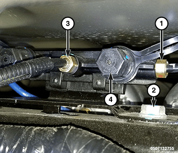
1 - Air Line Nut 2 - Fill Port Bracket Bolt 3 - Reservoir Air Line 4 - Reservoir Fill Connection Cap - Using Tool, Air Suspension Refill 10247B , remove the air hose from the quick coupler and connect the quick coupler to the air suspension reservoir fill connection and slowly open the valve by turning clockwise to exhaust the pressure from the reservoir.
- If the air suspension system is operable, use a scan tool, in the routines under the Air Suspension Control Module (ASCM), deflate the complete system to atmosphere.