Removal and Installation
Front Height Sensor
▸Contents: 02 - Front Suspension
- Special Tools
Air Suspension
- Warning
- Description and OperationAir Suspension
- Diagnosis And Testing
Standard Procedure
- Technical SpecificationsTorque Specifications
Air Line
COMPRESSOR ASSEMBLY, Air Suspension
HOSE ASSEMBLY, Air Suspension
RESERVOIR, Air Suspension
SENSOR, Height
Removal and Installation
Front, Independent Front Suspension
- Description and OperationFront Suspension
Diagnosis and Testing
- Technical SpecificationsTorque Specifications
ARM, Lower Control
Removal and Installation
ARM, Upper Control
Removal and Installation
BALL JOINT, Suspension, Lower
BALL JOINT, Suspension, Upper
KNUCKLE, Steering
LINK, Stabilizer Bar
Removal and Installation
SHOCK ABSORBER, Suspension
Removal and Installation
SPRING, Front
Removal and Installation
STABILIZER BAR, Front
Wheel Alignment
REMOVAL
| NOTE: |
The air suspension system can be disabled and enabled by using the Display Screen Module (DSM) in the vehicle under tire jack mode, which is the preferred method. If the disable level control routine in the scan tool is used it will only disable the level control (automatic and manual) for that ignition cycle. The air suspension system can also be enabled by driving the vehicle above 8 km/h (5 mph). The air suspension should be disabled prior to lifting the vehicle or performing any work. |
- Disable the air suspension system.
- Disconnect and isolate the negative battery cable(s) (Refer to 08 - Electrical/Battery System/Standard Procedure) .
- Raise and support the vehicle (Refer to 04 - Vehicle Quick Reference/Hoisting - Standard Procedure) .
- Disconnect the height sensor wire harness connector.
1 - Height Sensor Level Arm 2 - Height Sensor Bracket Bolt 3 - Height Sensor Wire Harness Connector - Carefully unsnap the upper end of the height sensor level arm from the ball stud of the upper control arm.
- Remove the height sensor bracket bolt.
- Remove the height sensor, bracket, and link.
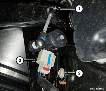
INSTALLATION
Follow the removal procedure in reverse for general reassembly of the components on the vehicle. The steps listed below are calling out specific procedures that should be followed during installation.
- Align the height sensor link with the ball stud on the upper control arm and press the link socket over the ball stud until it snaps into position.
- Perform the curb height measurement and record the values for input to the scan tool in the next step (Refer to 02 - Front Suspension/Wheel Alignment - Standard Procedure) .
- Verify the scan tool preferences are set to metric. When writing the measured values to the Air Suspension Control Module (ASCM) they will need to be in millimeters.
- Using a scan tool in Air Suspension Control Module (ASCM) perform the following:
- Perform the Write Suspension Height Values routine and input measurements recorded as prompted by scan tool.
- Command the vehicle to Normal Ride Height (NRH).
- Run the Air Mass Calculation routine on the air suspension system.
- Run the Height Sensor Check routine on the air suspension system.
- Enable Level Control.
- Perform the ASCM Verification Test (Refer to 28 - DTC-Based Diagnostics/MODULE, Air Suspension Control (ASCM) - Standard Procedure) .
 TORQUE SPECIFICATIONS - AIR SUSPENSION