Diagnosis And Testing
BALL JOINT, Suspension, Upper
▸Contents: 02 - Front Suspension
- Special Tools
Air Suspension
- Warning
- Description and OperationAir Suspension
- Diagnosis And Testing
Standard Procedure
- Technical SpecificationsTorque Specifications
Air Line
COMPRESSOR ASSEMBLY, Air Suspension
HOSE ASSEMBLY, Air Suspension
RESERVOIR, Air Suspension
SENSOR, Height
Removal and Installation
Front, Independent Front Suspension
- Description and OperationFront Suspension
Diagnosis and Testing
- Technical SpecificationsTorque Specifications
ARM, Lower Control
Removal and Installation
ARM, Upper Control
Removal and Installation
BALL JOINT, Suspension, Lower
BALL JOINT, Suspension, Upper
KNUCKLE, Steering
LINK, Stabilizer Bar
Removal and Installation
SHOCK ABSORBER, Suspension
Removal and Installation
SPRING, Front
Removal and Installation
STABILIZER BAR, Front
Wheel Alignment
- Raise and support the vehicle (Refer to 04 - Vehicle Quick Reference/Hoisting/Standard Procedure) .
- Remove the tire and wheel assembly (Refer to 22 - Tires and Wheels/Removal and Installation) .
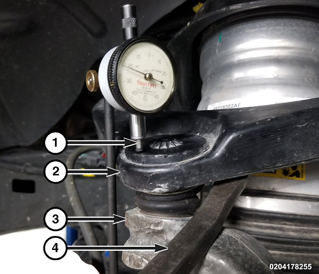
- Mount a dial indicator securely to the steering knuckle.
- Position dial indicator plunger (1) on the topside of the upper ball joint, and zero the dial indicator.
NOTE: Use care not to pry against or tear the ball joint boot when checking the free play.
- Position a pry bar (4) between the steering knuckle (3) and the upper control arm (2) and pry gently to check free play.
- If the travel exceeds 0.5 mm (0.020 in.), replace the upper control arm (Refer to 02 - Front Suspension/Front/ARM, Upper Control/Removal and Installation) .
- Install the tire and wheel assembly (Refer to 22 - Tires and Wheels/Removal and Installation) .
- Remove the support and lower vehicle.