Description and Operation
Front Suspension
▸Contents: 02 - Front Suspension
- Special Tools
Air Suspension
- Warning
- Description and OperationAir Suspension
- Diagnosis And Testing
Standard Procedure
- Technical SpecificationsTorque Specifications
Air Line
COMPRESSOR ASSEMBLY, Air Suspension
HOSE ASSEMBLY, Air Suspension
RESERVOIR, Air Suspension
SENSOR, Height
Removal and Installation
Front, Independent Front Suspension
- Description and OperationFront Suspension
Diagnosis and Testing
- Technical SpecificationsTorque Specifications
ARM, Lower Control
Removal and Installation
ARM, Upper Control
Removal and Installation
BALL JOINT, Suspension, Lower
BALL JOINT, Suspension, Upper
KNUCKLE, Steering
LINK, Stabilizer Bar
Removal and Installation
SHOCK ABSORBER, Suspension
Removal and Installation
SPRING, Front
Removal and Installation
STABILIZER BAR, Front
Wheel Alignment
DESCRIPTION
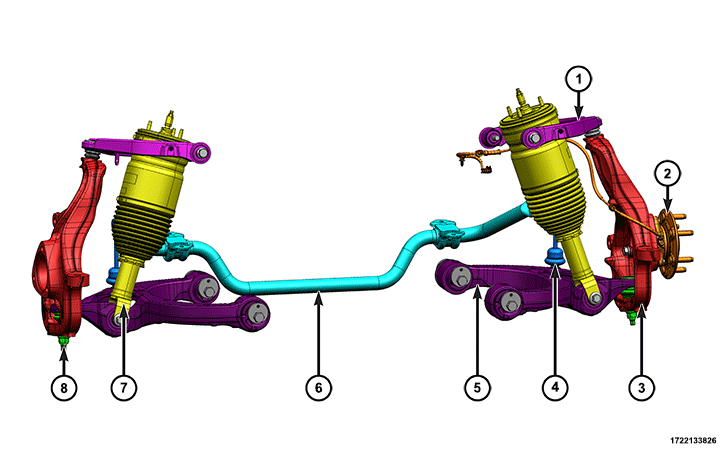 |
The front suspension includes the following components:
Component Index
|
1. |
|
|
2. |
|
|
3. |
|
|
4. |
|
|
5. |
|
|
6. |
|
|
7. |
|
|
8. |
The front suspension is designed to allow each wheel to adapt to different road surfaces independently. The wheels are mounted to hub and bearing units which are bolted to the steering knuckles. The double-row hub bearings are sealed and lubricated for life. The steering knuckles turn (pivot) on ball joints.
OPERATION
Air Spring / Coil Spring
The air springs on vehicles equipped with air suspension or the coil springs, support the vehicle weight.
Hub and Bearing
The hub and bearings are bolted to each steering knuckle and facilitate the mounting of the road wheels. The hub and bearings house the front wheel speed sensors.
Lower Ball Joint
The lower ball joints are housed in each of the lower control arms and are only serviced with the lower control arms. The lower ball joints provide an articulated mechanical connection between the lower control arms and the steering knuckle, they facilitate motion and travel of the steering knuckle.
Lower Control Arm
The lower control arms are constructed from aluminum. They are mounted on two pivot bolts and use rubber/urethane bushings for isolation and articulation. Each arm houses an lower ball joint which is only serviceable with the arm. Each lower control arms bolts to the air spring near the center on the arm. During wheel alignment the lower control arms are shifted by turning the lower control arm bolts and eccentrics to adjust camber and caster.
Stabilizer Bar
The stabilizer bar is constructed from steel. The bar mounts to the frame front crossmember through two rubber/urethane bushings and two steel mounting brackets. Stabilizer bar links are connected at each end. The stabilizer bar minimizes body roll during cornering.
Stabilizer Bar Link
The stabilizer bar links provide a mechanical connection between the stabilizer bar and the lower control arm. The stabilizer bar links have joints which facilitate axial articulation differences between the lower control arms and the stabilizer bar.
Steering Knuckle
The steering knuckles are constructed from aluminum and allow the front wheels to steer. They also feature mounting provisions for brake calipers and hub and bearings.
Upper Control Arm
The upper control arms have an inner steel frame and an outer plastic structure. They are mounted on two pivot bolts and use rubber/urethane bushings for isolation and articulation. Each arm houses an upper ball joint which is only serviceable with the arm. The upper arms feature a height sensor rod ball stud.
| NOTE: |
In any instance where a bolt is through a rubber bushing, the bolt must be torqued with the vehicle at normal ride height. |