Removal and Installation
Upper Control Arm Without Trx
▸Contents: 02 - Front Suspension
- Special Tools
Air Suspension
- Warning
- Description and OperationAir Suspension
- Diagnosis And Testing
Standard Procedure
- Technical SpecificationsTorque Specifications
Air Line
COMPRESSOR ASSEMBLY, Air Suspension
HOSE ASSEMBLY, Air Suspension
RESERVOIR, Air Suspension
SENSOR, Height
Removal and Installation
Front, Independent Front Suspension
- Description and OperationFront Suspension
Diagnosis and Testing
- Technical SpecificationsTorque Specifications
ARM, Lower Control
Removal and Installation
ARM, Upper Control
Removal and Installation
BALL JOINT, Suspension, Lower
BALL JOINT, Suspension, Upper
KNUCKLE, Steering
LINK, Stabilizer Bar
Removal and Installation
SHOCK ABSORBER, Suspension
Removal and Installation
SPRING, Front
Removal and Installation
STABILIZER BAR, Front
Wheel Alignment
REMOVAL
| NOTE: |
The air suspension system can be disabled and enabled by using the Display Screen Module (DSM) in the vehicle under tire jack mode, which is the preferred method. If the disable level control routine in the scan tool is used it will only disable the level control (automatic and manual) for that ignition cycle. The air suspension system can also be enabled by driving the vehicle above 8 km/h (5 mph). The air suspension should be disabled prior to lifting the vehicle or performing any work. |
- If equipped, disable the air suspension system.
- Raise and support the vehicle (Refer to 04 - Vehicle Quick Reference/Hoisting/Standard Procedure) .
- Remove the tire and wheel assembly (Refer to 22 - Tires and Wheels/Removal and Installation) .
- If equipped, disconnect the front height sensor rod from the upper control arm (Refer to 02 - Front Suspension/Air Suspension/SENSOR, Height Front/Removal and Installation) .
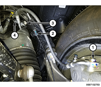
1 - Brake Hose Banjo Bolt 2 - Wheel Speed Sensor Wire Routing Clip 3 - Bolt 4 - Brake Line Flare Nut - Disconnect the wheel speed sensor wire routing clip from the upper control arm.
CAUTION: Never allow the disc brake caliper to hang from the brake hose. Damage to the brake hose will result. Provide a suitable support to hang the caliper securely.
- Remove the brake caliper adapter as an assembly with the brake caliper (Refer to 05 - Brakes, Base/Hydraulic/Mechanical/ADAPTER, Disc Brake Caliper/Removal and Installation) .
- Remove and DISCARD the upper ball joint nut.
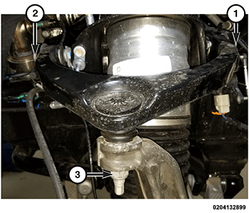
1 - Upper Control Arm Bolt 2 - Upper Control Arm Bolt 3 - Upper Ball Joint Nut - Separate upper ball joint from the steering knuckle with Ball Joint Remover Remover, Ball Joint 8677
- Remove the two upper control arm bolts and flag nuts.
- Remove upper control arm.
INSTALLATION
Follow the removal procedure in reverse for general reassembly of the components on the vehicle. The steps listed below are calling out specific procedures that should be followed during installation.
- In any instance where a bolt is through a rubber bushing, the bolt must be torqued with the vehicle at normal ride height.
- Install the two upper control arm bolts and flag nuts but do not tighten at this time .
- Insert the ball joint in the steering knuckle then install the NEW upper ball joint nut and tighten to the proper (Torque Specifications) .
- Tighten the two upper control arm bolts to the proper (Torque Specifications) .
- Perform the toe adjustment procedure (Refer to 02 - Front Suspension/Wheel Alignment - Standard Procedure) .