Removal and Installation
Coil Over With Trx
▸Contents: 02 - Front Suspension
- Special Tools
Air Suspension
- Warning
- Description and OperationAir Suspension
- Diagnosis And Testing
Standard Procedure
- Technical SpecificationsTorque Specifications
Air Line
COMPRESSOR ASSEMBLY, Air Suspension
HOSE ASSEMBLY, Air Suspension
RESERVOIR, Air Suspension
SENSOR, Height
Removal and Installation
Front, Independent Front Suspension
- Description and OperationFront Suspension
Diagnosis and Testing
- Technical SpecificationsTorque Specifications
ARM, Lower Control
Removal and Installation
ARM, Upper Control
Removal and Installation
BALL JOINT, Suspension, Lower
BALL JOINT, Suspension, Upper
KNUCKLE, Steering
LINK, Stabilizer Bar
Removal and Installation
SHOCK ABSORBER, Suspension
Removal and Installation
SPRING, Front
Removal and Installation
STABILIZER BAR, Front
Wheel Alignment
REMOVAL
- Disconnect and isolate the negative battery cable(s) (Refer to 08 - Electrical/Battery System/Standard Procedure) .
- Raise and support the vehicle (Refer to 04 - Vehicle Quick Reference/Hoisting/Standard Procedure) .
- Remove the tire and wheel assembly (Refer to 22 - Tires and Wheels/Removal and Installation) .
- Remove the caliper adapter as an assembly with the brake caliper (Refer to 05 - Brakes, Base/Hydraulic/Mechanical/ADAPTER, Disc Brake Caliper/Removal and Installation) .
- Disengage the wheel speed sensor wire harness.
- Disconnect the stabilizer bar link from the lower control arm (Refer to 02 - Front Suspension/Front/LINK, Stabilizer Bar/Removal and Installation) .
- Remove the halfshaft (Refer to 03 - Differential and Driveline/SHAFTS, Axle/Drive/Half/Removal and Installation) .
- Remove the front skid plate (Refer to 13 - Frame and Bumpers/Under Body Protection/PLATE, Skid, Front/Removal and Installation) .
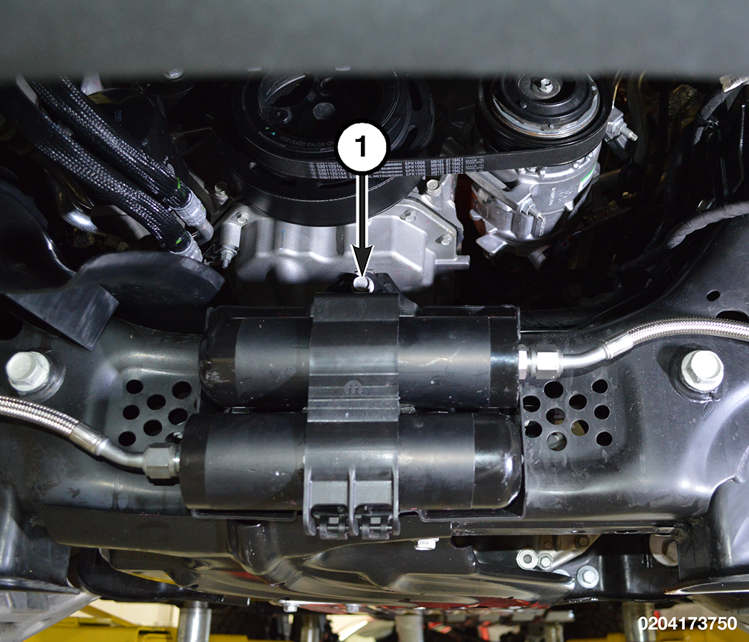
- Remove the reservoir bracket bolt.
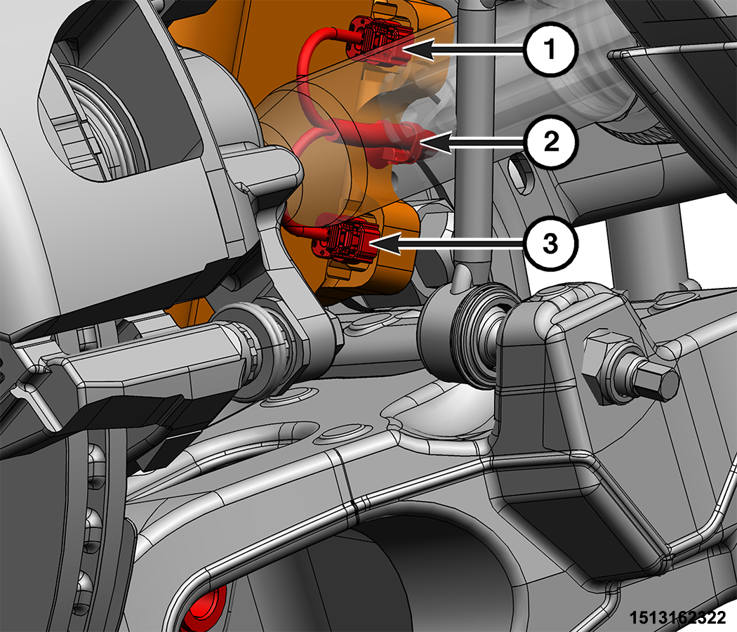
1 - Reservoir Bracket Bolt - Disconnect the shock absorber wire harness connectors.
1 - Wire Harness Connector 2 - Wire Harness Routing Clip 3 - Wire Harness Connector - Disengage the wire harness routing clip.
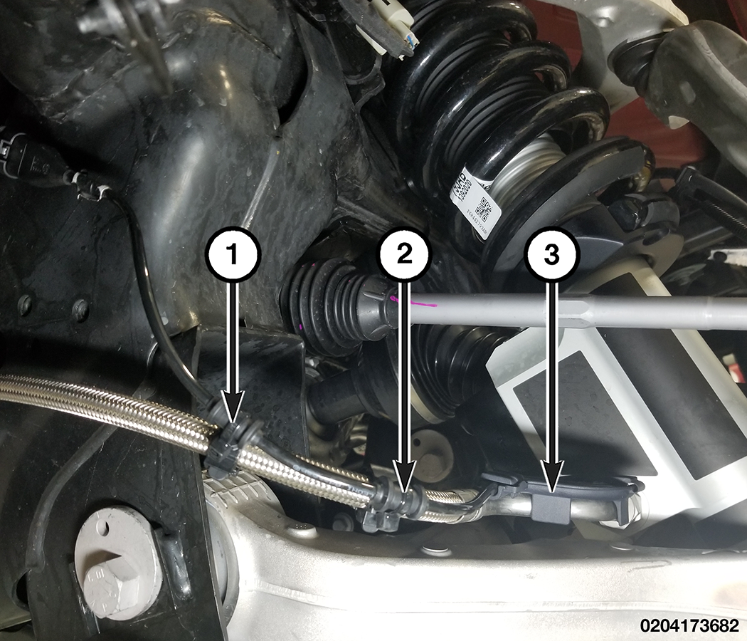
- Disengage the wire harness routing clips.
1 - Wire Harness Routing Clip 2 - Wire Harness Routing Clip 3 - Wire Harness Routing Clip - Support the lower control arm outboard end.
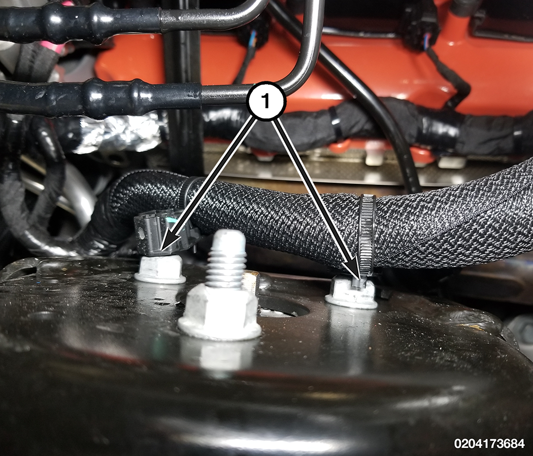
- If equipped, disengage the wire harness routing clips.
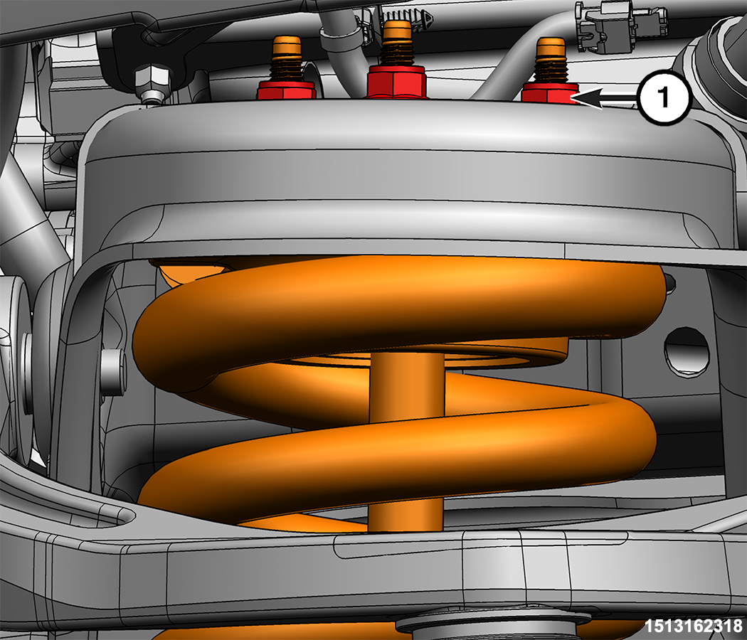
1 - Wire Harness Routing Clips - Remove the three shock absorber upper nuts.
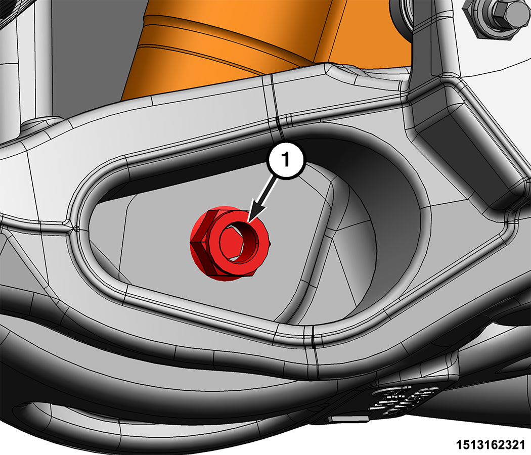
1 - Shock Absorber Upper Nuts - Remove the shock absorber lower nut and bolt.
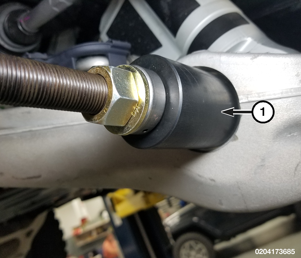
1 - Shock Absorber Lower Nut - Use Remover, Lower Shock Sleeve 2074100020 to retract the lower control arm shock bolt sleeve until the lower control arm will separate from the shock absorber.
CAUTION: Never allow the disc brake caliper to hang from the brake hose. Damage to the brake hose will result. Provide a suitable support to hang the caliper securely.
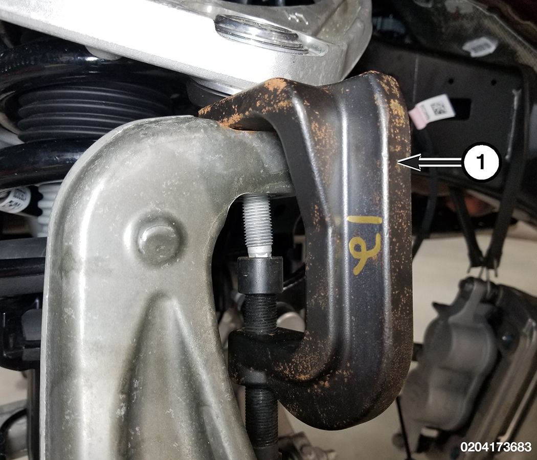
1 - Lower Shock Sleeve Remover - Remove the upper ball joint nut and separate the upper ball joint from the knuckle using Remover, Ball Joint 8677 .
1 - Ball Joint Remover - Remove the shock absorber.
- Compress the coil spring in a suitable spring compressor.
CAUTION: Never use impact or high speed tools to remove the strut rod nut. Damage to the strut internal bearings can occur.
- Have a helper support the shock absorber from below, hold the strut rod with a suitable socket then use tool Kit, Remover - Installer Shock / Strut 2027800020 to remove the strut rod nut.
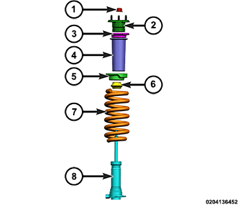
1 - Strut Rod Nut 5 - Spring Isolator 2 - Upper Strut Mount 6 - Jounce Bumper 3 - Upper Spacer 7 - Spring 4 - Shield 8 - Shock Absorber - Remove the upper strut mount, the upper spacer, the shield, the spring isolator, the jounce bumper, and the shock absorber.
- Release the spring compressor and remove the coil spring from the strut spring compressor.
INSTALLATION
| NOTE: |
In any instance where a bolt is through a rubber bushing, the bolt must be torqued with the vehicle at normal ride height. |
- Compress the coil spring in a suitable strut spring compressor.
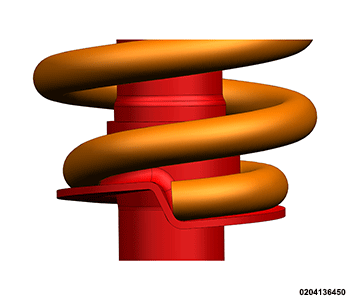
- Have a helper position the shock absorber to the coil spring from below and verify that the coil spring lower end is correctly aligned to the spring stop as shown.
- Install the jounce bumper, the spring isolator, the shield, the upper spacer, the upper strut mount, and the strut rod nut.
CAUTION: Never use impact or high speed tools to remove the strut rod nut. Damage to the strut internal bearings can occur.
1 - Strut Rod Nut 5 - Spring Isolator 2 - Upper Strut Mount 6 - Jounce Bumper 3 - Upper Spacer 7 - Spring 4 - Shield 8 - Shock Absorber - Have a helper support the shock absorber from below, hold the strut rod with a suitable socket then use Kit, Remover - Installer Shock / Strut 2027800020 to install the strut rod nut and tighten to the proper (Torque Specifications) .
- Release the spring compressor and remove the strut assembly from the strut spring compressor.
- Position the lower control arm to the shock absorber.
1 - Shock Absorber Lower Nut - Install the shock absorber lower bolt and the shock absorber lower nut and tighten to the proper (Torque Specifications) .
NOTE: The shock absorber lower bolt and nut are only tightened temporarily to seat the lower shock bushing.
- Loosen the shock absorber lower nut.
- Position the coil over shock assembly in the strut tower.
1 - Shock Absorber Upper Nuts - Install the three shock absorber upper nuts and tighten to the proper (Torque Specifications) .
- If equipped, secure the wire harness routing clips.
1 - Wire Harness Routing Clips - Insert the upper ball joint stud into the steering knuckle then install the upper ball joint nut and tighten to the proper (Torque Specifications) .
- Secure the wire harness routing clips.
1 - Wire Harness Routing Clip 2 - Wire Harness Routing Clip 3 - Wire Harness Routing Clip - Connect the shock absorber wire harness connectors.
1 - Wire Harness Connector 2 - Wire Harness Routing Clip 3 - Wire Harness Connector - Secure the wire harness routing clip.
- Position the shock absorber reservoir to the bracket.
1 - Reservoir Bracket Bolt - Install the reservoir bracket bolt and tighten to the proper (Torque Specifications) .
- Install the front skid plate (Refer to 13 - Frame and Bumpers/Under Body Protection/PLATE, Skid, Front/Removal and Installation) .
- Install the half shaft (Refer to 03 - Differential and Driveline/SHAFTS, Axle/Drive/Half/Removal and Installation) .
- Connect the stabilizer bar link to the lower control arm (Refer to 02 - Front Suspension/Front/LINK, Stabilizer Bar/Removal and Installation) .
- Secure the wheel speed sensor harness.
- Install the caliper adapter with the caliper as an assembly (Refer to 05 - Brakes, Base/Hydraulic/Mechanical/ADAPTER, Disc Brake Caliper/Removal and Installation) .
- Remove the support from the lower control arm outboard end.
- Install the tire and wheel assembly (Refer to 22 - Tires and Wheels/Removal and Installation) .
- Remove the support and lower the vehicle.
- Tighten the shock absorber lower nut to the proper (Torque Specifications) .
1 - Shock Absorber Lower Nut - Connect the negative battery cable(s) (Refer to 08 - Electrical/Battery System/Standard Procedure) .