Standard Procedure
Alignment
▸Contents: 02 - Front Suspension
- Special Tools
Air Suspension
- Warning
- Description and OperationAir Suspension
- Diagnosis And Testing
Standard Procedure
- Technical SpecificationsTorque Specifications
Air Line
COMPRESSOR ASSEMBLY, Air Suspension
HOSE ASSEMBLY, Air Suspension
RESERVOIR, Air Suspension
SENSOR, Height
Removal and Installation
Front, Independent Front Suspension
- Description and OperationFront Suspension
Diagnosis and Testing
- Technical SpecificationsTorque Specifications
ARM, Lower Control
Removal and Installation
ARM, Upper Control
Removal and Installation
BALL JOINT, Suspension, Lower
BALL JOINT, Suspension, Upper
KNUCKLE, Steering
LINK, Stabilizer Bar
Removal and Installation
SHOCK ABSORBER, Suspension
Removal and Installation
SPRING, Front
Removal and Installation
STABILIZER BAR, Front
Wheel Alignment
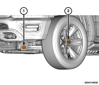 |
|
|
| 1 - Front Lower Control Arm Bolt |
| 2 - Wheel Center |
Camber and caster angle adjustments involve changing the position of the lower control arm through adjusting eccentrics on the lower control arm bolts. The vehicle should be at normal ride height.
CASTER
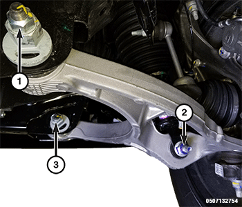 |
|
|
| 1 - Lower Control Arm Nut |
| 2 - Shock Absorber Lower Bolt |
| 3 - Lower Control Arm Nut |
To Adjust Caster:
Moving the front or rear position of the lower control arm in or out, will change the caster angle and camber angle significantly. To maintain the camber angle while adjusting caster, move one pivot bolt of the lower control arm in or out. Then move the other pivot bolt of the lower control arm in the opposite direction.
To decrease positive caster angle, move the rear position of the lower control arm inward (toward the engine). Move the front of the lower control arm outward (away from the engine) slightly until the desired caster angle is obtained.
To increase positive caster angle, move the rear position of the lower control arm outward (away from the engine). Move the front of the lower control arm inward (toward the engine) slightly until the desired caster angle is obtained.
After the adjustment is made, tighten the lower control arm nuts to the proper torque specifications.
CAMBER
|
|
|
| 1 - Lower Control Arm Nut |
| 2 - Shock Absorber Lower Bolt |
| 3 - Lower Control Arm Nut |
To Adjust Camber:
Move both pivot bolts of the lower control arm together in or out. This will change the camber angle significantly and have little effect on the caster angle.
After the adjustment is made, tighten the lower control arm nuts to the proper torque specifications.
TOE
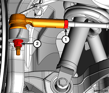 |
|
|
| 1 - Tie Rod Jam Nut |
| 2 - Nut |
The wheel toe position adjustment is the final adjustment.
To Adjust Toe:
- Start the engine and turn the wheels left and right to the full lock position before straightening the wheels. Secure the steering wheel with the front wheels in the straight-ahead position.
- Loosen the tie rod jam nuts.
NOTE: Each front wheel should be adjusted for one half of the total toe position specification. This will ensure the steering wheel will be centered when the wheels are positioned straight ahead.
- Adjust the wheel toe position by turning the inner tie rod as necessary.
- Tighten the tie rod jam nut to the proper torque specifications. Verify the toe setting does not change during tightening.
- Verify the toe specifications are correct.
- Using the scan tool select: "Electronic Power Steering (EPS)", "Miscellaneous Functions", "Steering Angle Calibration", and follow the prompts to calibrate the steering angle.
TORQUE SPECIFICATIONS - FRONT SUSPENSION
|
DESCRIPTION |
SPECIFICATION |
COMMENT |
|---|---|---|
|
Active Damping Sensor Nut |
9 N·m (80 In. Lbs.) |
– |
|
Halfshaft Nut |
250 N·m (184 Ft. Lbs.) |
Do not reuse these fasteners. If removed, a new fastener must be installed and tightened to specifications. |
|
Hub And Bearing Bolts |
50 + 165° N·m (37 + 165° Ft. Lbs.) |
– |
|
Lower Ball Joint Nut |
51 + 195° N·m (38 + 195° Ft. Lbs.) |
Do not reuse these fasteners. If removed, a new fastener must be installed and tightened to specifications. |
|
Lower Control Arm Nuts (Old Style With Silver Coating) |
100 + 145° N·m (74 + 145° Ft. Lbs.) |
– |
|
Lower Control Arm Nuts (New Style With Pink Coating) |
100 + 145° N·m (74 + 145° Ft. Lbs.) |
– |
|
Lower Control Arm Nuts (RHO) (Old Style With Silver Coating) |
100 + 148° N·m (74 + 148° Ft. Lbs.) |
– |
|
Lower Control Arm Nuts (RHO) (New Style With Pink Coating) |
100 + 148° N·m (74 + 148° Ft. Lbs.) |
– |
|
Reservoir Bracket Bolt |
21 N·m (15 Ft. Lbs.) |
– |
|
Reservoir Bracket Clamp Bolt |
18 N·m (13 Ft. Lbs.) |
– |
|
Reservoir Hose Bolt |
30 N·m (22 Ft. Lbs.) |
– |
|
Ride Height Sensor Stud (RHO) |
11 N·m (8 Ft. Lbs.) |
– |
|
Strut Rod Nut |
35 N·m (26 Ft. Lbs.) |
– |
|
Strut Rod Nut (RHO) |
119 N·m (88 Ft. Lbs.) |
– |
|
Shock Absorber Lower Nut |
168 N·m (124 Ft. Lbs.) |
– |
|
Shock Absorber Lower Nut (RHO) |
138 + 305° N·m (102 + 305° Ft. Lbs.) |
– |
|
Upper Shock Mount to Frame |
63 N·m (46 Ft. Lbs.) |
Do not reuse these fasteners. If removed, a new fastener must be installed and tightened to specifications. |
|
Shock to Mount Assembly |
35 N·m (26 Ft. Lbs.) |
Do not reuse these fasteners. If removed, a new fastener must be installed and tightened to specifications. |
|
Shock Absorber Upper Nut |
70 N·m (52 Ft. Lbs.) |
– |
|
Stabilizer Bar Bolts |
45 N·m (33 Ft. Lbs.) |
– |
|
Stabilizer Bar Bolts (RHO) |
30 + 97° N·m (22 + 97° Ft. Lbs.) |
– |
|
Stabilizer Bar Link Lower Nut - 2019 to 2020 |
119 N·m (88 Ft. Lbs.) |
– |
|
Stabilizer Bar Link Lower Nut - 2021 and forward |
110 N·m (81 Ft. Lbs.) |
– |
|
Stabilizer Bar Link Lower Nut (RHO) |
115 N·m (85 Ft. Lbs.) |
– |
|
Stabilizer Bar Link Upper Nut (18mm) - 2019 to 2020 |
93 N·m (69 Ft. Lbs.) |
Do not reuse these fasteners. If removed, a new fastener must be installed and tightened to specifications. |
|
Stabilizer Bar Link Upper Nut (19mm) - 2019 to 2020 |
100 N·m (74 Ft. Lbs.) |
Do not reuse these fasteners. If removed, a new fastener must be installed and tightened to specifications. |
|
Stabilizer Bar Link Upper Nut - 2021 and forward |
155 N·m (114 Ft. Lbs.) |
Do not reuse these fasteners. If removed, a new fastener must be installed and tightened to specifications. |
|
Stabilizer Bar Link Upper Nut (RHO) |
115 N·m (85 Ft. Lbs.) |
– |
|
Upper Control Arm Bolts |
174 N·m (128 Ft. Lbs.) |
– |
|
Upper Ball Joint Nut |
35 + 180° N·m (26 + 180° Ft. Lbs.) |
Do not reuse these fasteners. If removed, a new fastener must be installed and tightened to specifications. |
TORQUE SPECIFICATIONS - STEERING GEAR
|
DESCRIPTION |
SPECIFICATION |
COMMENT |
|---|---|---|
|
Inner Tie Rod End To Steering Gear |
90 N·m (66 Ft. Lbs.) |
– |
|
Steering Gear Mounting Bolts |
160 + 90° N·m (118 + 90° Ft. Lbs.) |
Do not reuse these fasteners. If removed, a new fastener must be installed and tightened to specifications. |
|
Tie Rod End to Knuckle Nut |
55 + 180° N·m (41 + 180° Ft. Lbs.) |
Do not reuse these fasteners. If removed, a new fastener must be installed and tightened to specifications. |
|
Tie Rod Jam Nut |
85 N·m (63 Ft. Lbs.) |
– |