Removal and Installation
Master Cylinder Brake
▸Contents: 05 - Brakes
05 - Brakes, ABS
- Description and OperationAnti-Lock Brake System (Abs)
- Standard ProcedureStandard Procedure - Antilock Brake System Bleeding
- Technical SpecificationsTorque Specifications
Electrical
SENSOR, Wheel Speed, Front
SENSOR, Wheel Speed, Rear
SWITCH, Electronic Stability Program (ESP)
Hydraulic/Mechanical
Integrated Control Unit (Icu)
Removal and Installation
Hydraulic Control Unit (Hcu)
Removal and Installation
05 - Brakes, Base
- Warning
- Caution
- DescriptionBase Brake System
- Diagnosis And Testing
- Standard ProcedureBrake System Bleeding
- Special Tools
Technical Specifications
Electrical
SWITCH, Brake Fluid Level
Removal and Installation
SWITCH, Adjustable Pedals
PUMP, Electric Vacuum
- SENSOR, Vacuum PressureRemoval And Installation
Hydraulic/Mechanical
ADAPTER, Disc Brake Caliper
Removal and Installation
CALIPER, Disc Brake, Front
CALIPER, Disc Brake, Rear
MASTER CYLINDER, Brake
PADS, Brake, Front
PADS, Brake, Rear
PEDAL(S), Brake and/or Accelerator
ROTOR, Brake
- Diagnosis and TestingDiagnosis And Testing - Disc Brake Rotor
Removal and Installation
Parking Brake
- Description And Operation
ACTUATOR, Electric Park Brake
SWITCH, Electric Park Brake
REMOVAL
- Press the brake pedal five times to deplete any vacuum that may remain in the booster unit.
- Disconnect and isolate the negative battery cable(s) (Refer to 08 - Electrical/Battery System/Standard Procedure) .
- Remove the brake fluid level switch from the brake fluid reservoir (Refer to 05 - Brakes, Base/Electrical/SWITCH, Brake Fluid Level/Removal and Installation) .
- Remove the master cylinder brake line flare nuts from the master cylinder and gently position the brake lines clear of the master cylinder.
1 - Vacuum Pressure Sensor Wire Harness Connector 2 - Brake Fluid Switch Wire Harness Connector 3 - Master Cylinder Brake Line Flare Nuts 4 - Master Cylinder Nuts 5 - Brake Fluid Reservoir Bolts - Remove and DISCARD the master cylinder nuts.
NOTE: Gently ease the master cylinder away from the brake booster. During removal, the master cylinder should be pulled straight away from the brake booster to avoid excess interference with the brake booster output rod and in order not to dislodge the output rod from its seat inside the brake booster.
- Remove the master cylinder.
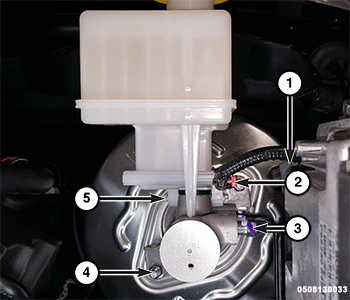
INSTALLATION
Follow the removal procedure in reverse for general reassembly of the components on the vehicle. The steps listed below are calling out specific procedures that should be followed during installation.
- Be certain the output rod of the brake booster is in position and retained by a output rod retaining ring by looking into the boosters master cylinder mounting hole. This position will enable the output rod to enter inside of the master cylinder plunger sleeve during installation. Proper position is obtained when the output rod is centered perpendicular to the master cylinder mounting hole.
- Prior to installing the master cylinder assembly check that there is a vacuum seal present at the shoulder of the master cylinder flange and its neck. A square seal must be present to ensure vacuum integrity with the booster.
- Take precautions to locate the master cylinder plunger over the booster output rod before installing the master cylinder. If correctly fitted, the master cylinder should easily engage with the brake booster output rod before the mounting studs are engaged in the flange holes of the master cylinder.
- Install NEW master cylinder nuts.
- Fill and bleed the base brake system (Refer to 05 - Brakes - Standard Procedure) .
- Start the engine and let it idle for 30 seconds, then turn off the engine and wait approximately 1 minute. Fully stroke brake pedal to assure there are several strokes with assist prior to depletion of vacuum. If not, check for missing seal between master cylinder and booster.