Description And Operation
Parking Brake
▸Contents: 05 - Brakes
05 - Brakes, ABS
- Description and OperationAnti-Lock Brake System (Abs)
- Standard ProcedureStandard Procedure - Antilock Brake System Bleeding
- Technical SpecificationsTorque Specifications
Electrical
SENSOR, Wheel Speed, Front
SENSOR, Wheel Speed, Rear
SWITCH, Electronic Stability Program (ESP)
Hydraulic/Mechanical
Integrated Control Unit (Icu)
Removal and Installation
Hydraulic Control Unit (Hcu)
Removal and Installation
05 - Brakes, Base
- Warning
- Caution
- DescriptionBase Brake System
- Diagnosis And Testing
- Standard ProcedureBrake System Bleeding
- Special Tools
Technical Specifications
Electrical
SWITCH, Brake Fluid Level
Removal and Installation
SWITCH, Adjustable Pedals
PUMP, Electric Vacuum
- SENSOR, Vacuum PressureRemoval And Installation
Hydraulic/Mechanical
ADAPTER, Disc Brake Caliper
Removal and Installation
CALIPER, Disc Brake, Front
CALIPER, Disc Brake, Rear
MASTER CYLINDER, Brake
PADS, Brake, Front
PADS, Brake, Rear
PEDAL(S), Brake and/or Accelerator
ROTOR, Brake
- Diagnosis and TestingDiagnosis And Testing - Disc Brake Rotor
Removal and Installation
Parking Brake
- Description And Operation
ACTUATOR, Electric Park Brake
SWITCH, Electric Park Brake
DESCRIPTION
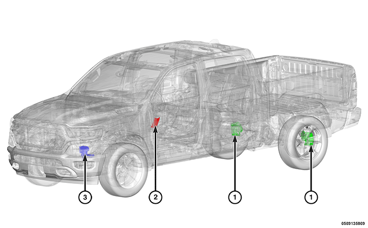 |
The Electric Parking Brake (EPB) system consists of the following components:
Component Index
|
1. |
|
|
2. |
|
|
3. |
The EPB is a software function performed within the ABS module. The purpose of the EPB is to replace the traditional manually operated park brake hardware in a vehicle. It replaces the traditional manually pulled lever system pulling a cable attached to the brake with an electronic switch and computer controlled actuator fixed to the brake. The system provides a number of safety functions, designed to protect the vehicle and pedestrians, or as degraded modes of operation designed to keep the vehicle operational after fault. In addition to manually applying and releasing the park brake on the driver's command.
OPERATION
The system uses the switch on the central tunnel and two electromechanical actuators, each installed on a rear brake caliper. If the vehicle is in motion, pull up and hold the button to engage the parking brake for any eventuality. The system will operate by increasing the hydraulic pressure. If the vehicle is stationary, it is only necessary to pull the button upwards once to engage the parking brake. To release the parking brake, press the brake pedal and press the parking brake button downwards. The Drive Away Release (DAR) function automatically releases the electric parking brake if the seat belt is fastened, a gear is engaged and the accelerator is pressed in order to move the vehicle. The safe hold function occurs when the vehicle speed is lower than 5 km/h (3 mph), the vehicle is not in the P ark position, and the driver door is ajar will cause the EPB system to apply the parking brake to stop the vehicle safely. The auto apply function occurs when the vehicle speed is lower than approximately 3 km/h (2 mph) and the automatic transmission is set to P ark will then cause the EPB system to apply the parking brake automatically. The status of the EPB functions can be configured in the dedicated Uconnect® system menu.
EPB can be applied by the following five ways and shall follow the priority as defined:
- Switch action
- Auto Park Brake function (APB)
- Vehicle Safe Hold function (VSH)
- External Command function
- Request from external system by Controller Area Network (CAN) signals from the Traction Control Module (TCM)
EPB can be released by three ways and shall follow the priority defined:
Antilock Brake System (ABS) Module
The ABS module performs the following:
- Receive command from driver by switch which is a hardwire connection
- Receive brake command through CAN bus from external system
- Drives an LED light on EPB switch by hardwire connection.
- Doing Dynamic Braking either by ESC function or EPB function
- Doing all conditions check and control motors on Calipers to engage or disengage park brake.
- Brake System provides vehicle/wheel speed signals to EPB function
- EPB system can provides rear parking brake service/maintenance function per customer selection through personal setting menu on the Radio
The ABS module receives the following:
CAN-C Inputs
- Vehicle configuration data
- Engine Stop Start (ESS) feature present
- Odometer reading
- Drivetrain Control Module (DTCM) EPB hold request
- P R N D status
- Target gear
- Commanded ignition switch status
- Driver seat belt status
- Static / Effective engine torque
- Expected engine torque based on target engine speed
- Accelerator pedal position
- Accelerator pedal position sensor fault
- ESS engine state
- ESS active EPB status
- Engine Revolutions Per Minute (RPM)
- Engine running state
- Driver door ajar status (open or closed)
Hardwire Inputs
The ABS module provides the following:
CAN-C Outputs
- Reason EPB active
- EPB switch position
- EPB service status
- EPB clamp force
- Text message display request
- Status of the EPB service mode
- Status of the EPB auto park brake function availability
- Status of the EPB hold function
- EPB warning (fault) lamp activation request
- EPB function lamp active request
Hardwire Outputs
- Park brake driver for left and right motor on caliper
- Park brake motor active or not active status
- Park brake switch indicator LED ON/OFF
Body Control Module (BCM)
The BCM is the gateway for CAN-C to CAN-IHS messages.
The BCM receives the following:
CAN-C Inputs
- Text message display request
- Status of the EPB service mode
- Status of the EPB auto park brake function availability
- Status of the EPB hold function
The BCM provides the following:
CAN-IHS Outputs
- Text message display request
- Status of the EPB service mode
- Status of the EPB auto park brake function availability
- Status of the EPB hold function
EPB Actuators
When the ABS module receives a request through the EPB switch or through CAN signal and there is no internal fault to prevent the EPB action, the EPB will process this request immediately. If the request is coming from the EPB switch, the ABS module will check current EPB state and decide what action the EPB will apply. The ABS module will change internal signals and the motors will start to move. During the motors moving period (either applying or releasing), the ABS module will set the EPB state to temporary state (applying/releasing) for about 1-2 seconds. Then ABS module will change to a stable state either Applied, Released or Unknown after this short time.
The EPB Actuators receives the following:
Hardwire Inputs
EPB Switch
The EPB system uses a manual push-pull switch to control the EPB Apply/Release. Each time the EPB switch is pressed, the internal signal should change and the EPB state should be convert to a different state if there is no internal fault to prevent it. Once the EPB switch is released, the internal signal should change, the previous switch request ends, and the EPB switch is ready for the next request.
The EPB Switch module receives the following:
Hardwire Outputs
Hardwire Inputs
Instrument Panel Cluster (IPC)
The IPC receives the following:
CAN-C Inputs
- EPB warning (fault) lamp activation request
- EPB function lamp active request
- Text message display request
Radio
The radio provides the ability for personal settings for EPB Auto Park functions and provides the Service Mode functions selection. The radio also provides feedback to the customer.
The Radio receives the following:
CAN-IHS Inputs