Removal and Installation
Pedal Assembly
▸Contents: 05 - Brakes
05 - Brakes, ABS
- Description and OperationAnti-Lock Brake System (Abs)
- Standard ProcedureStandard Procedure - Antilock Brake System Bleeding
- Technical SpecificationsTorque Specifications
Electrical
SENSOR, Wheel Speed, Front
SENSOR, Wheel Speed, Rear
SWITCH, Electronic Stability Program (ESP)
Hydraulic/Mechanical
Integrated Control Unit (Icu)
Removal and Installation
Hydraulic Control Unit (Hcu)
Removal and Installation
05 - Brakes, Base
- Warning
- Caution
- DescriptionBase Brake System
- Diagnosis And Testing
- Standard ProcedureBrake System Bleeding
- Special Tools
Technical Specifications
Electrical
SWITCH, Brake Fluid Level
Removal and Installation
SWITCH, Adjustable Pedals
PUMP, Electric Vacuum
- SENSOR, Vacuum PressureRemoval And Installation
Hydraulic/Mechanical
ADAPTER, Disc Brake Caliper
Removal and Installation
CALIPER, Disc Brake, Front
CALIPER, Disc Brake, Rear
MASTER CYLINDER, Brake
PADS, Brake, Front
PADS, Brake, Rear
PEDAL(S), Brake and/or Accelerator
ROTOR, Brake
- Diagnosis and TestingDiagnosis And Testing - Disc Brake Rotor
Removal and Installation
Parking Brake
- Description And Operation
ACTUATOR, Electric Park Brake
SWITCH, Electric Park Brake
REMOVAL
| NOTE: |
If the brake pedal is being replaced, the brake booster pushrod retainer and cup must be replaced also. |
| NOTE: |
The views in this procedure show a vehicle equipped with adjustable pedals. Vehicles without adjustable pedals are similar. |
- Disconnect and isolate the negative battery cable(s) (Refer to 08 - Electrical/Battery System/Standard Procedure) .
- Remove the Powertrain Control Module (PCM) (Refer to 08 - Electrical/8E - Electronic Control Modules/MODULE, Powertrain Control/Removal and Installation) .
- Disconnect the brake fluid level sensor wire harness connector.
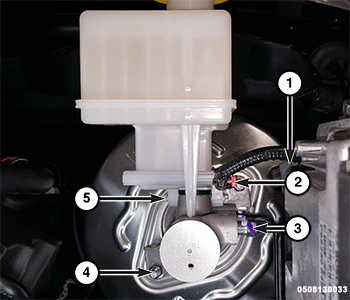
1 - Vacuum Pressure Sensor Wire Harness Connector 2 - Brake Fluid Switch Wire Harness Connector 3 - Master Cylinder Brake Line Flare Nuts 4 - Master Cylinder Nuts 5 - Brake Fluid Reservoir Bolts - Remove the master cylinder nuts and position the master cylinder aside.
- Remove the steering column opening cover (Refer to 23 - Body/Instrument Panel/COVER, Steering Column Opening/Removal and Installation) .
- Remove the accelerator pedal (Refer to 09 - Engine/Fuel System/PEDAL, Accelerator/Removal and Installation) .
- Remove the brake booster (Refer to 05 - Brakes/BOOSTER, Brake/Removal and Installation) .
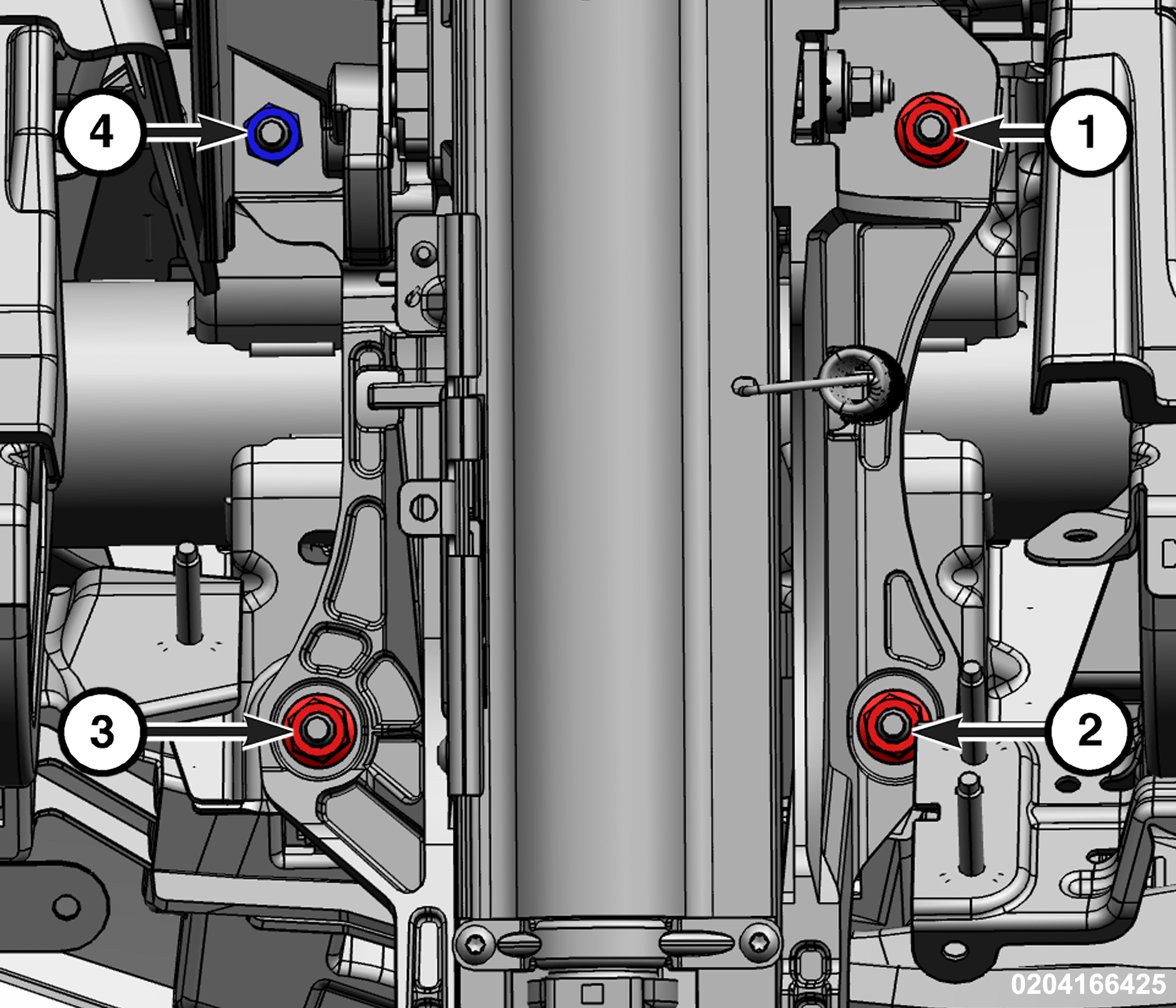
- Remove the steering column nuts.
1 - Steering Column Nut 2 - Steering Column Nut 3 - Steering Column Nut 4 - Column Nut - Loosen, but do not remove the column nut.
- Position the steering column aside.
- Disengage the wire harness routing clips from the left side of the pedal assembly.
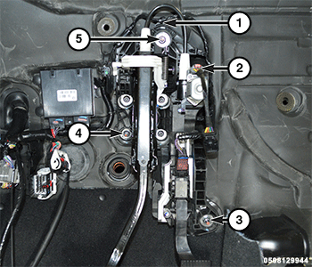
- Remove and DISCARD the two pedal sled nuts and lower the pedal assembly to the floor.
1 - Wire Harness Routing Clips 2 - Motor Wire Harness Connector 3 - Pedal Sled Fastener 4 - Brake Booster Nuts 5 - Pedal Sled Fastener - Remove the stop lamp sensor (Refer to 08 - Electrical/Lamps/Lighting - Exterior/SENSOR, Stop Lamp/Removal and Installation) .
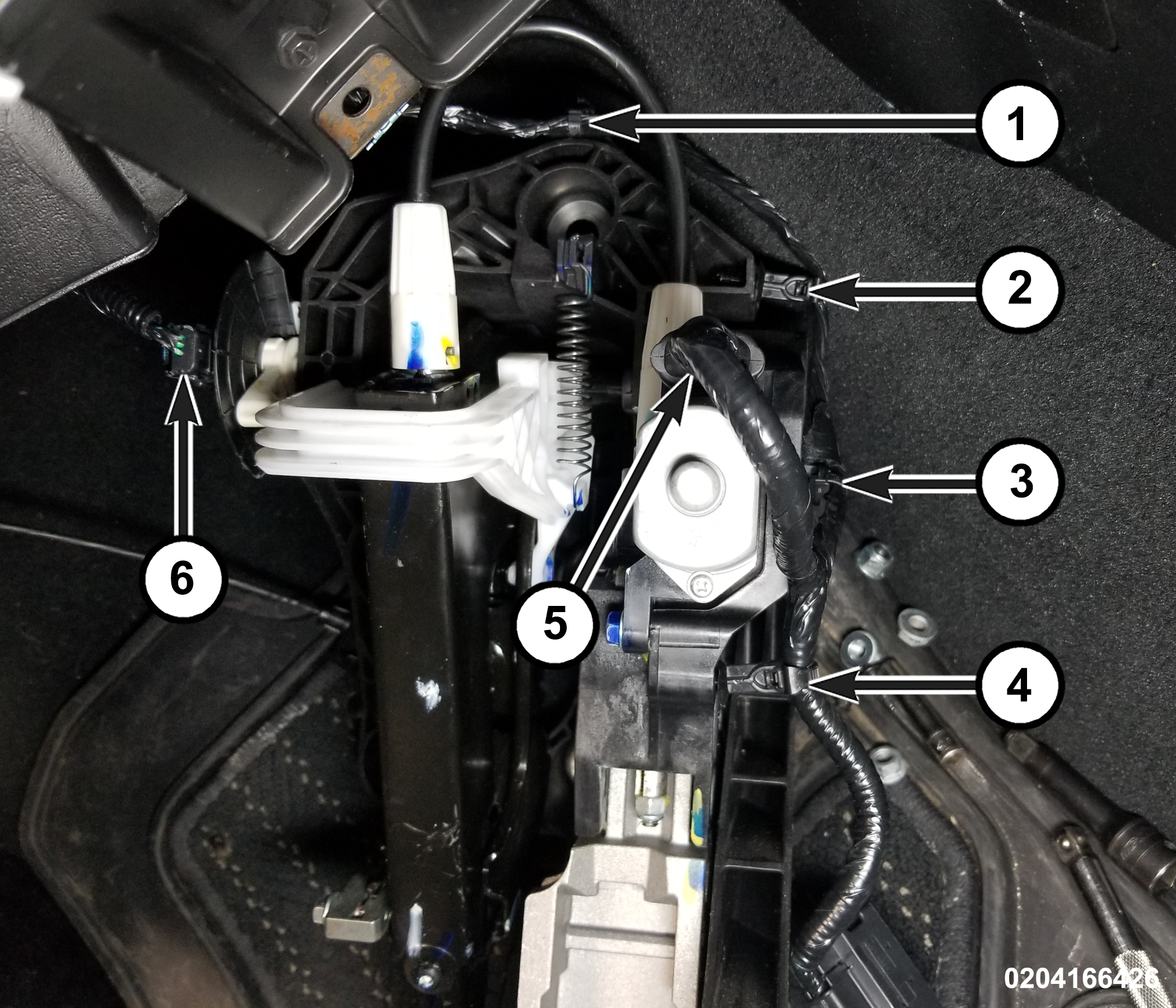
- Disengage the wire harness routing clips.
1 - Wire Harness Routing Clip 4 - Wire Harness Routing Clip 2 - Wire Harness Routing Clip 5 - Pedal Adjustment Motor Wire Harness Connector 3 - Wire Harness Routing Clip 6 - Wire Harness Connector - Disconnect the pedal adjustment motor wire harness connector.
- Remove the pedal assembly.
INSTALLATION
Follow the removal procedure in reverse for general reassembly of the components on the vehicle. The steps listed below are calling out specific procedures that should be followed during installation.