Description
Base Brake System
▸Contents: 05 - Brakes
05 - Brakes, ABS
- Description and OperationAnti-Lock Brake System (Abs)
- Standard ProcedureStandard Procedure - Antilock Brake System Bleeding
- Technical SpecificationsTorque Specifications
Electrical
SENSOR, Wheel Speed, Front
SENSOR, Wheel Speed, Rear
SWITCH, Electronic Stability Program (ESP)
Hydraulic/Mechanical
Integrated Control Unit (Icu)
Removal and Installation
Hydraulic Control Unit (Hcu)
Removal and Installation
05 - Brakes, Base
- Warning
- Caution
- DescriptionBase Brake System
- Diagnosis And Testing
- Standard ProcedureBrake System Bleeding
- Special Tools
Technical Specifications
Electrical
SWITCH, Brake Fluid Level
Removal and Installation
SWITCH, Adjustable Pedals
PUMP, Electric Vacuum
- SENSOR, Vacuum PressureRemoval And Installation
Hydraulic/Mechanical
ADAPTER, Disc Brake Caliper
Removal and Installation
CALIPER, Disc Brake, Front
CALIPER, Disc Brake, Rear
MASTER CYLINDER, Brake
PADS, Brake, Front
PADS, Brake, Rear
PEDAL(S), Brake and/or Accelerator
ROTOR, Brake
- Diagnosis and TestingDiagnosis And Testing - Disc Brake Rotor
Removal and Installation
Parking Brake
- Description And Operation
ACTUATOR, Electric Park Brake
SWITCH, Electric Park Brake
DESCRIPTION
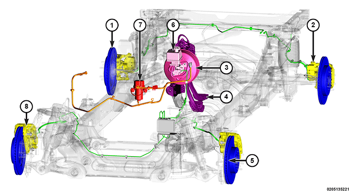 |
The base brake system consists of the following major components:
Component Index
|
1. |
Brake Rotor – Rear |
|
2. |
Disc Brake Caliper – Rear with Electric Parking Brake (EPB) actuator |
|
3. |
|
|
4. |
|
|
5. |
Brake Rotor – Front |
|
6. |
|
|
7. |
|
|
8. |
Disc Brake Caliper – Front |
OPERATION
Power assist front disc and rear disc brakes are standard equipment. Disc brake components consist of dual piston front calipers and ventilated front rotors, and single piston rear calipers, with EPB actuators, and ventilated rear rotors.
A dual diaphragm vacuum power brake booster is used for all applications. Gasoline powered engines use engine vacuum obtained from the intake manifold as the main source of vacuum for the power brake booster, however, diesel engines have a mechanical vacuum pump as the main vacuum source. The base brake system for all models uses an EVP for additional vacuum supply.
All models have an aluminum master cylinder with plastic reservoir.
Factory brake lining on all models consists of an organic base material combined with metallic particles. The original equipment linings do not contain asbestos.
The braking force of the rear wheels is monitored and adjusted by Electronic Brake Distribution (EBD). The EBD functions like a rear proportioning valve. The EBD system uses the Antilock Brake System (ABS) to control the slip of the rear wheels in partial braking range. The braking force of the rear wheels is controlled electronically by using the inlet and outlet valves located in the Hydraulic Control Unit (HCU).
Brake Master Cylinder
 |
||||
|
||||
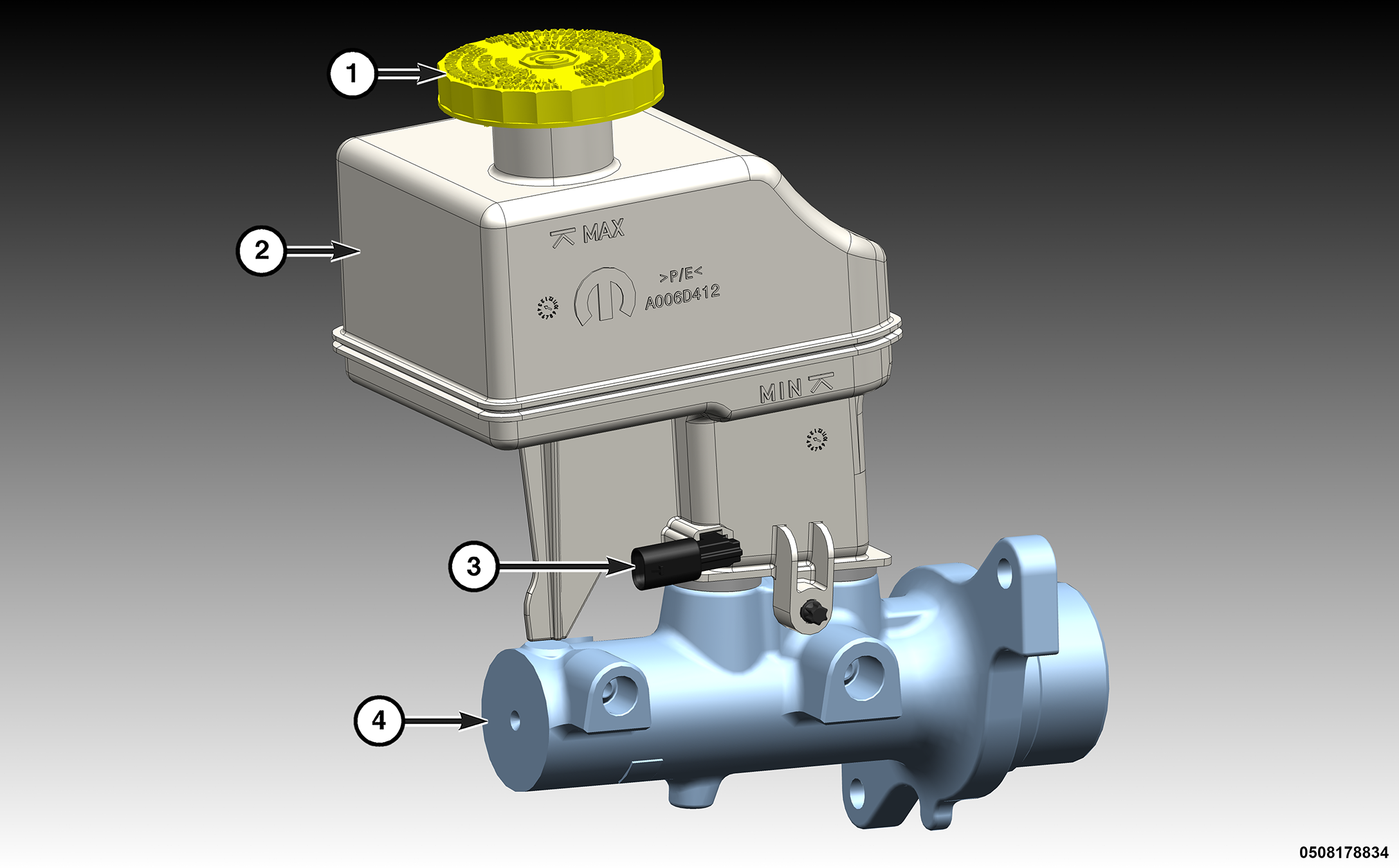
The master cylinder used for all applications has an aluminum body and nylon reservoir with single filler cap. A fluid level indicator is mounted to the side of the reservoir.
The master cylinder bore contains a primary and secondary piston. The primary piston supplies hydraulic pressure to the front brakes. The secondary piston supplies hydraulic pressure to the rear brakes.
A two-piece master cylinder is used on all models. The cylinder body containing the primary and secondary pistons is made of aluminum. The removable fluid reservoir is made of nylon reinforced with glass fiber. The reservoir stores reserve brake fluid for the hydraulic brake circuits and has a switch for indicating low fluid levels.
The fluid compartments of the nylon reservoir are interconnected to permit fluid level equalization. However, the equalization feature does not affect circuit separation in the event of a front or rear brake malfunction. The reservoir compartments will retain enough fluid to operate the functioning hydraulic circuit.
Care must be exercised when removing/installing the master cylinder brake connecting lines. The threads in the cylinder fluid ports can be damaged if care is not exercised. Start all brake line fittings by hand to avoid cross threading.
The fluid reservoir can be replaced if necessary. However, the aluminum body section of the master cylinder is not a repairable component.
| NOTE: |
If diagnosis indicates that an internal master cylinder malfunction has occurred, the aluminum body section must be replaced as an assembly. |
Brake Pedal Assembly
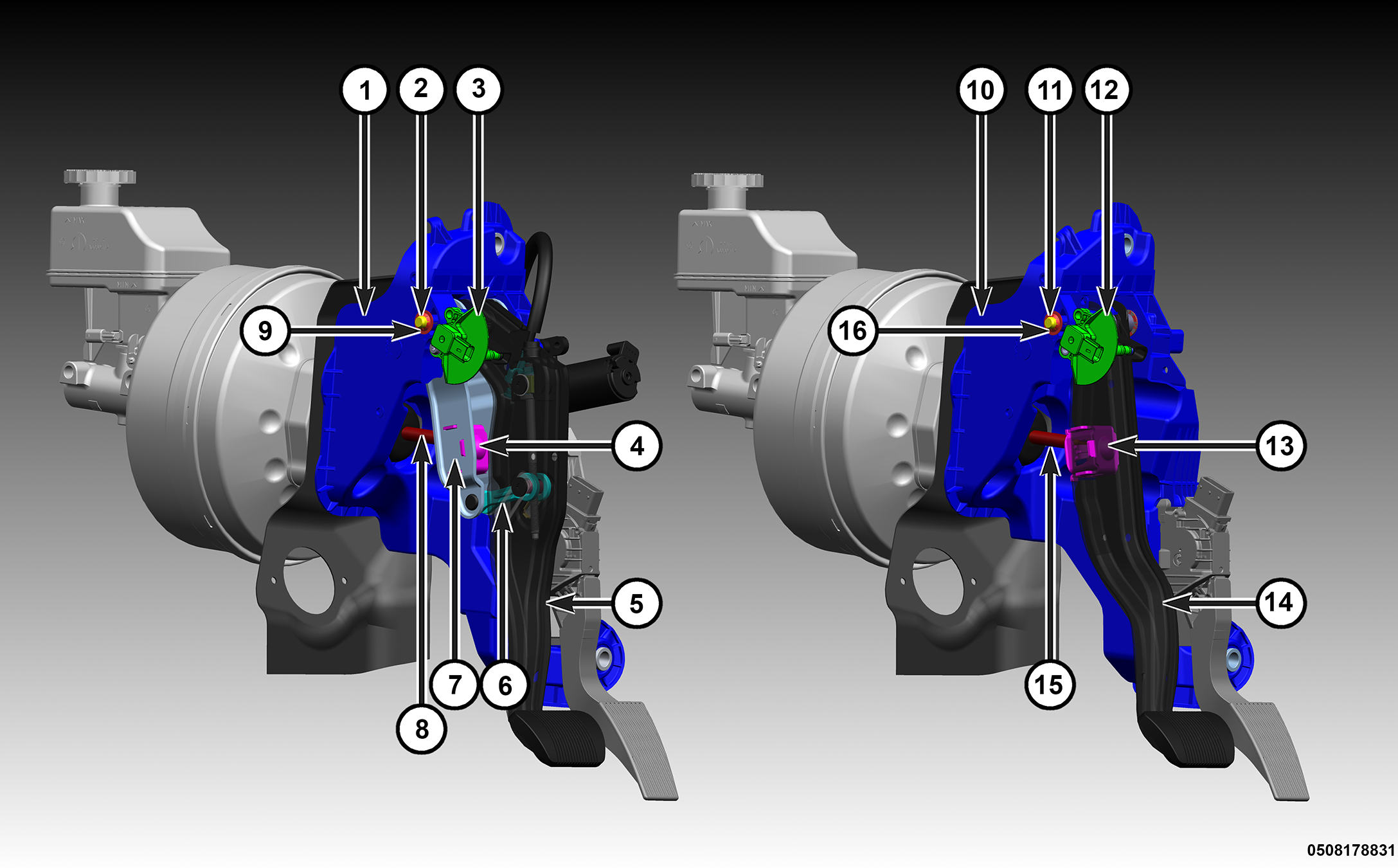
A suspended-type brake pedal is used on all models, whether adjustable or non-adjustable. If any of the pivot shaft bushings become dry, a spray lubricant can be used to eliminate noises.
Adjustable Brake Pedal
On adjustable pedal models, the pedal is attached to the pedal support bracket with a pivot shaft pin, bushings and one starlock clip. The power booster push rod is attached to the pedal pivot brace with a master cylinder push rod pin connector, which is secured to the pedal pivot brace. The pedal pivot brace is attached to the brake pedal with the pedal adjuster rod. The master cylinder push rod pin connector and the brake pedal position sensor are the only separately serviceable components on the brake pedal assembly. The accelerator pedal assembly is serviced separately from the brake pedal assembly as well. The brake pedal is serviced with the adjustable (drive) cable (from the adjustable pedal motor). For brake pedal replacement with adjustable pedals, the assembly must be removed from the vehicle. Adjustable pedal components can be serviced as follows:
- Adjustable pedal assembly (including bracket and all subcomponents)
- Brake pedal assembly (including adjustment cable)
- Accelerator pedal (Electronic Throttle Control/ETC)
- Accelerator subassembly (including adjustable pedal motor, ETC, ETC mounting plate and bracket).
Non-Adjustable Brake Pedal
On non-adjustable models, the pedal is attached to the pedal support bracket with a pivot shaft pin, bushings and one starlock clip. The power booster push rod is attached to the pedal with a master cylinder push rod pin connector, which is secured to the brake pedal.
When the pedal is pressed, the power brake booster push rod is also pressed which moves the power brake booster internal diaphragm rod. The power brake booster internal diaphragm rod pushes and moves the master cylinder piston.
The master cylinder push rod pin connector and the brake pedal position sensor are the only separately serviceable components on the brake pedal assembly. The accelerator pedal assembly is serviced separately from the brake pedal assembly as well.
Brake Rotor
Ventilated front and rear disc brake rotors are standard equipment on this vehicle.
Disc Brake Caliper
 |
|||||
|
|||||
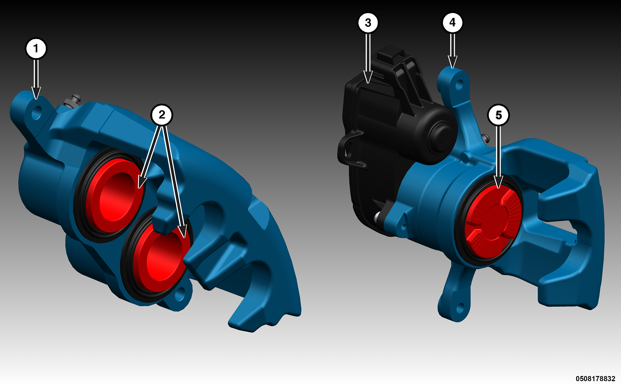
Dual piston disc brake calipers are used on the front. Single piston disc brake calipers are used on the rear. The calipers are free to slide laterally, which allows continuous compensation for lining wear. The rear brake calipers provide the mounting and connection points for the EPB actuators.
| NOTE: |
Petroleum based grease should not be used on any of the rubber components of the caliper. Use only Non-Petroleum based grease. |
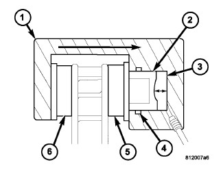 |
When the brakes are applied, fluid pressure is exerted against the caliper piston (2). The fluid pressure is exerted equally and in all directions. This means pressure exerted against the caliper piston and within the caliper bore will be equal.
Fluid pressure applied to the piston is transmitted directly to the inboard brake pad (5). This forces the inboard pad lining against the inboard surface of the disc brake rotor. At the same time, fluid pressure within the piston bore forces the caliper to slide inward on the mounting bolts. This action brings the outboard brake pad lining (6) into contact with the outboard surface of the disc brake rotor.
In summary, fluid pressure acting simultaneously on both piston and caliper, produces a strong clamping action. When sufficient force is applied, friction will attempt to stop the rotors from turning and bring the vehicle to a stop.
Application and release of the brake pedal generates only a very slight movement of the caliper and piston. Upon release of the pedal, the caliper and piston return to a rest position. The brake pads do not retract an appreciable distance from the rotor. In fact, clearance is usually at, or close to zero. The reasons for this are to keep road debris from getting between the rotor and lining and in wiping the rotor surface clear each revolution.
The caliper piston seal (4) controls the amount of piston (2) extension needed to compensate for normal lining wear.
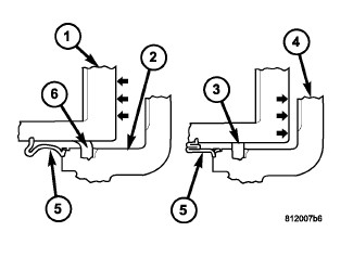 |
During brake application, the seal is deflected outward (6) by fluid pressure and piston movement. When the brakes (and fluid pressure) are released, the seal relaxes (3) and retracts the piston (1).
The amount of piston retraction is determined by the amount of seal deflection. Generally the amount is just enough to maintain contact between the piston and inboard brake pad.
Electric Vacuum Pump (EVP)
 |
||||
|
||||
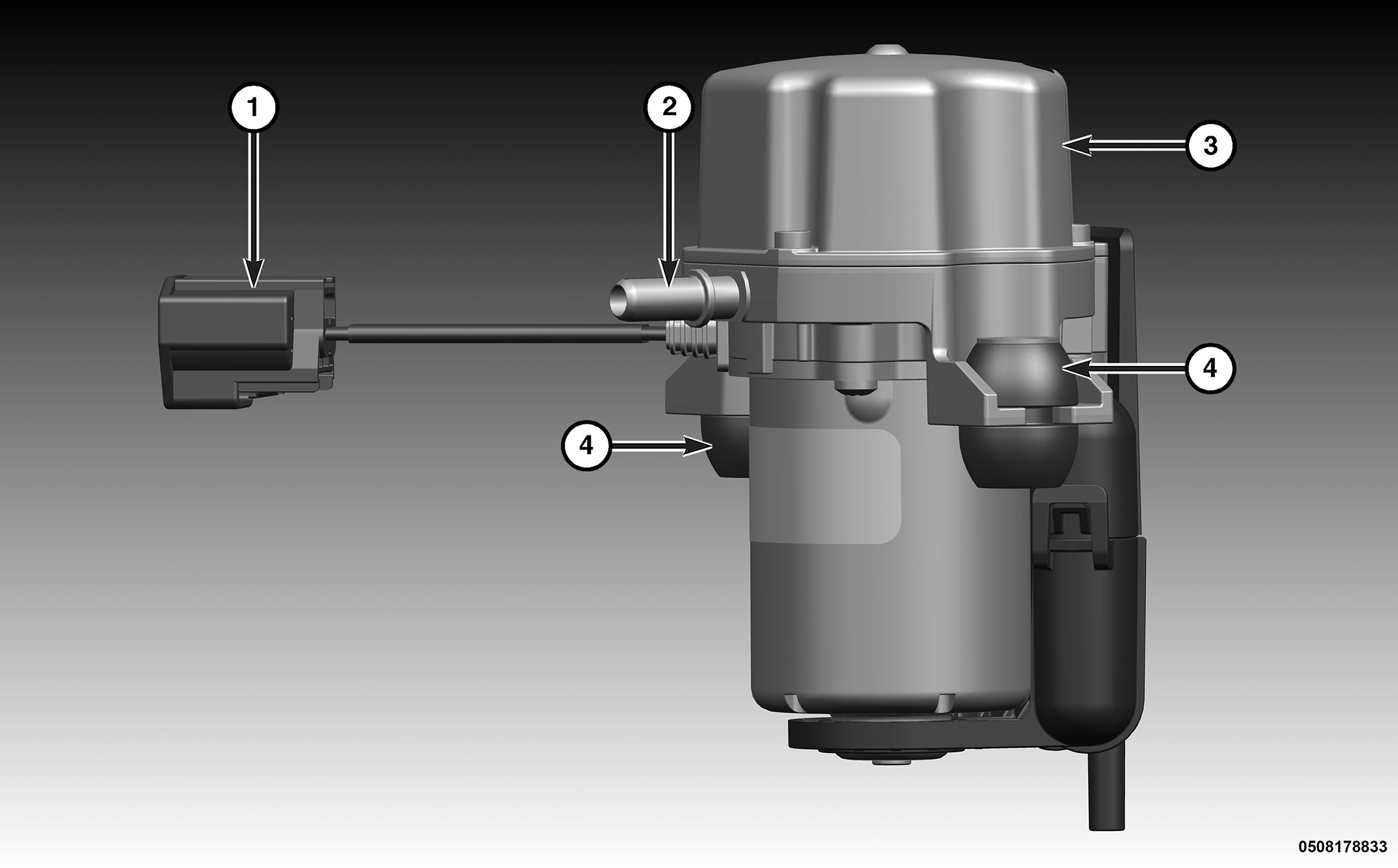
The EVP, located on the front of the engine, assists the vacuum system in maintaining adequate vacuum to the power brake booster under all operating conditions. The EVP has a pigtail connector. The EVP mounts to a bracket with two rubber insulators to reduce vibration, and the bracket mounts to the front of the engine. The vacuum hose has a quick-connect type fitting with a locking tab at the EVP. An inline vacuum check valve prevents the loss of vacuum in the power brake booster that might be caused by a fault in the EVP.
Power Brake Booster
 |
||||
|
||||
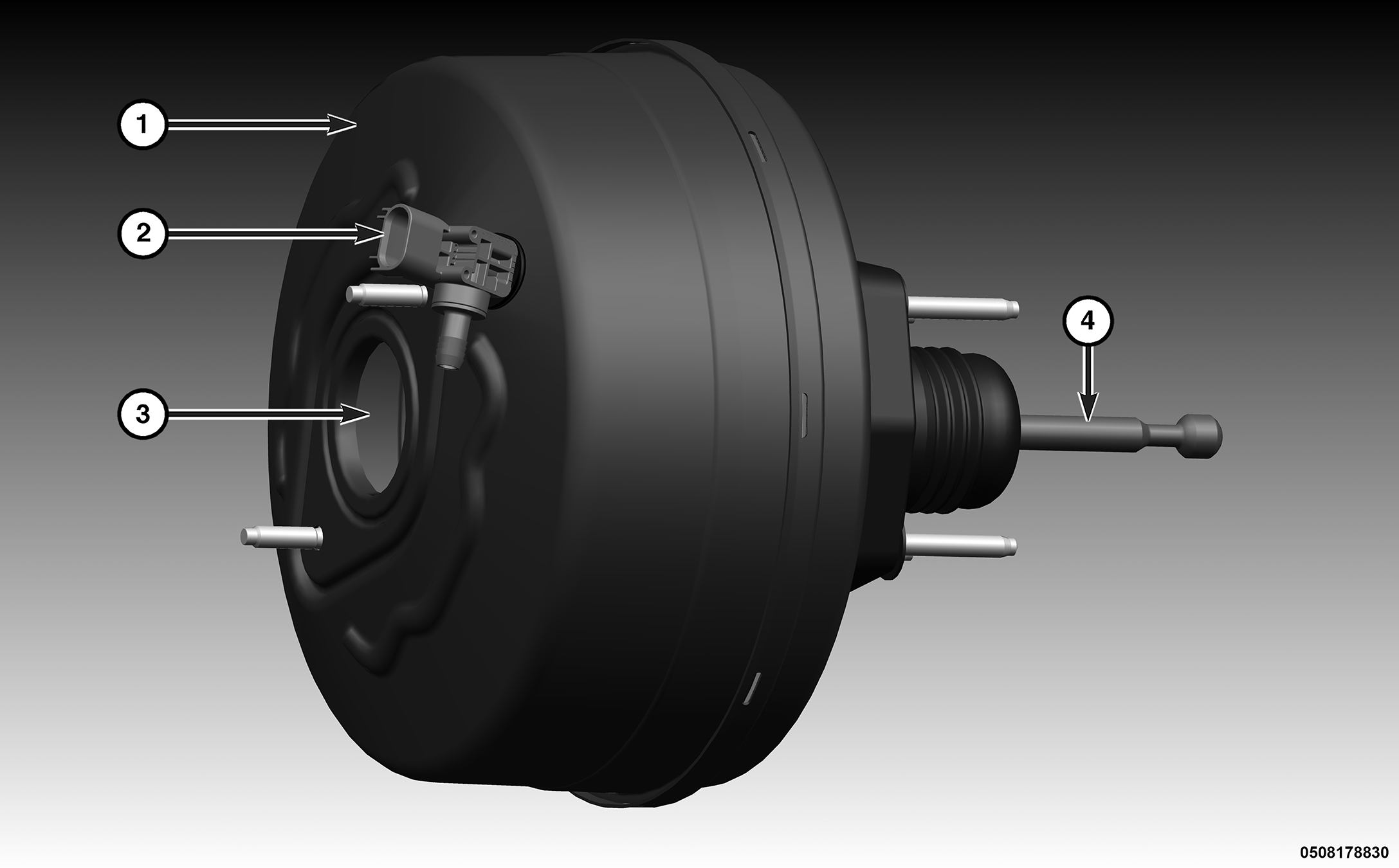
Power brake assist is supplied by a vacuum operated, dual diaphragm power brake booster. The power brake booster is mounted to the engine side of the bulkhead. The master cylinder is bolted to the front of the booster.
The power brake booster consists of a single housing divided into two chambers by a tandem diaphragm. The outer edge of the diaphragm is secured to the housing. The booster push rod, which connects the booster to the brake pedal and master cylinder, is attached to the center of the diaphragm. Power assist is generated by utilizing a combination of vacuum and atmospheric pressure to boost brake assist. A check valve sensor is attached to the booster, sealed with a grommet, and is connected to the vacuum supply hose. The vacuum supply hose is connected via a T-fitting to the engine vacuum source and the EVP. The engine vacuum source originates at the intake manifold on gasoline engines or the engine mechanical vacuum pump on diesel applications. The vacuum hoses incorporate inline check valves to prevent the loss of vacuum to the power brake booster should the engine shut off or the EVP stop working.
The power brake booster is not a repairable component. The power brake booster must be replaced as an assembly if diagnosis indicates a malfunction has occurred.