Removal and Installation
Rear Brake Caliper
▸Contents: 05 - Brakes
05 - Brakes, ABS
- Description and OperationAnti-Lock Brake System (Abs)
- Standard ProcedureStandard Procedure - Antilock Brake System Bleeding
- Technical SpecificationsTorque Specifications
Electrical
SENSOR, Wheel Speed, Front
SENSOR, Wheel Speed, Rear
SWITCH, Electronic Stability Program (ESP)
Hydraulic/Mechanical
Integrated Control Unit (Icu)
Removal and Installation
Hydraulic Control Unit (Hcu)
Removal and Installation
05 - Brakes, Base
- Warning
- Caution
- DescriptionBase Brake System
- Diagnosis And Testing
- Standard ProcedureBrake System Bleeding
- Special Tools
Technical Specifications
Electrical
SWITCH, Brake Fluid Level
Removal and Installation
SWITCH, Adjustable Pedals
PUMP, Electric Vacuum
- SENSOR, Vacuum PressureRemoval And Installation
Hydraulic/Mechanical
ADAPTER, Disc Brake Caliper
Removal and Installation
CALIPER, Disc Brake, Front
CALIPER, Disc Brake, Rear
MASTER CYLINDER, Brake
PADS, Brake, Front
PADS, Brake, Rear
PEDAL(S), Brake and/or Accelerator
ROTOR, Brake
- Diagnosis and TestingDiagnosis And Testing - Disc Brake Rotor
Removal and Installation
Parking Brake
- Description And Operation
ACTUATOR, Electric Park Brake
SWITCH, Electric Park Brake
REMOVAL
| CAUTION: |
Never allow the disc brake caliper to hang from the brake hose. Damage to the brake hose will result. Provide a suitable support to hang the caliper securely. |
| CAUTION: |
If the Electric Park Brake (EPB) switch is actuated with the caliper removed from the caliper bracket and still connected electrically, the EPB motor will fully extend causing damage to the caliper piston. Disconnect and isolate the negative battery cable. If equipped with an Intelligent Battery Sensor (IBS), disconnect the IBS connector first before disconnecting the negative battery cable. |
- Place the Electric Park Brake (EPB) in service mode.
- Using a brake pedal holding tool, depress the brake pedal past its first inch of travel and hold it in this position. Holding the brake pedal in this position will isolate the master cylinder from the hydraulic brake system and will not allow brake fluid to drain out of the brake fluid reservoir while brake lines are open.
- Raise and support the vehicle (Refer to 04 - Vehicle Quick Reference/Hoisting/Standard Procedure) .
- Remove the tire and wheel assembly (Refer to 22 - Tires and Wheels/Removal and Installation) .
- Remove the rear brake hose banjo bolt and DISCARD the copper washers.
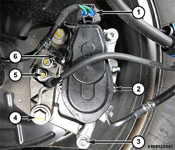
1 - EPB Actuator Wire Harness Connector 4 - Bolt 2 - EPB Actuator Screws 5 - Rear Wheel Speed Sensor Bolt 3 - Rear Caliper Bolts 6 - Wire Harness Routing Clip - Remove the rear caliper bolts.
- Disconnect the EPB actuator wire harness connector and disengage the wire harness routing clip.
- Remove the brake caliper.
INSTALLATION
Follow the removal procedure in reverse for general reassembly of the components on the vehicle. The steps listed below are calling out specific procedures that should be followed during installation.
| CAUTION: |
Verify that the brake hose is not twisted or kinked before tightening banjo bolt. |
- Position the rear brake hose to the brake caliper with NEW copper washers.
- Perform the brake bleeding standard procedure (Refer to 05 - Brakes, Base/Standard Procedure) .
- Apply brake pressure several times to seat the brake pads and obtain a firm brake pedal.