Description and Operation
Anti-Lock Brake System (Abs)
▸Contents: 05 - Brakes
05 - Brakes, ABS
- Description and OperationAnti-Lock Brake System (Abs)
- Standard ProcedureStandard Procedure - Antilock Brake System Bleeding
- Technical SpecificationsTorque Specifications
Electrical
SENSOR, Wheel Speed, Front
SENSOR, Wheel Speed, Rear
SWITCH, Electronic Stability Program (ESP)
Hydraulic/Mechanical
Integrated Control Unit (Icu)
Removal and Installation
Hydraulic Control Unit (Hcu)
Removal and Installation
05 - Brakes, Base
- Warning
- Caution
- DescriptionBase Brake System
- Diagnosis And Testing
- Standard ProcedureBrake System Bleeding
- Special Tools
Technical Specifications
Electrical
SWITCH, Brake Fluid Level
Removal and Installation
SWITCH, Adjustable Pedals
PUMP, Electric Vacuum
- SENSOR, Vacuum PressureRemoval And Installation
Hydraulic/Mechanical
ADAPTER, Disc Brake Caliper
Removal and Installation
CALIPER, Disc Brake, Front
CALIPER, Disc Brake, Rear
MASTER CYLINDER, Brake
PADS, Brake, Front
PADS, Brake, Rear
PEDAL(S), Brake and/or Accelerator
ROTOR, Brake
- Diagnosis and TestingDiagnosis And Testing - Disc Brake Rotor
Removal and Installation
Parking Brake
- Description And Operation
ACTUATOR, Electric Park Brake
SWITCH, Electric Park Brake
DESCRIPTION
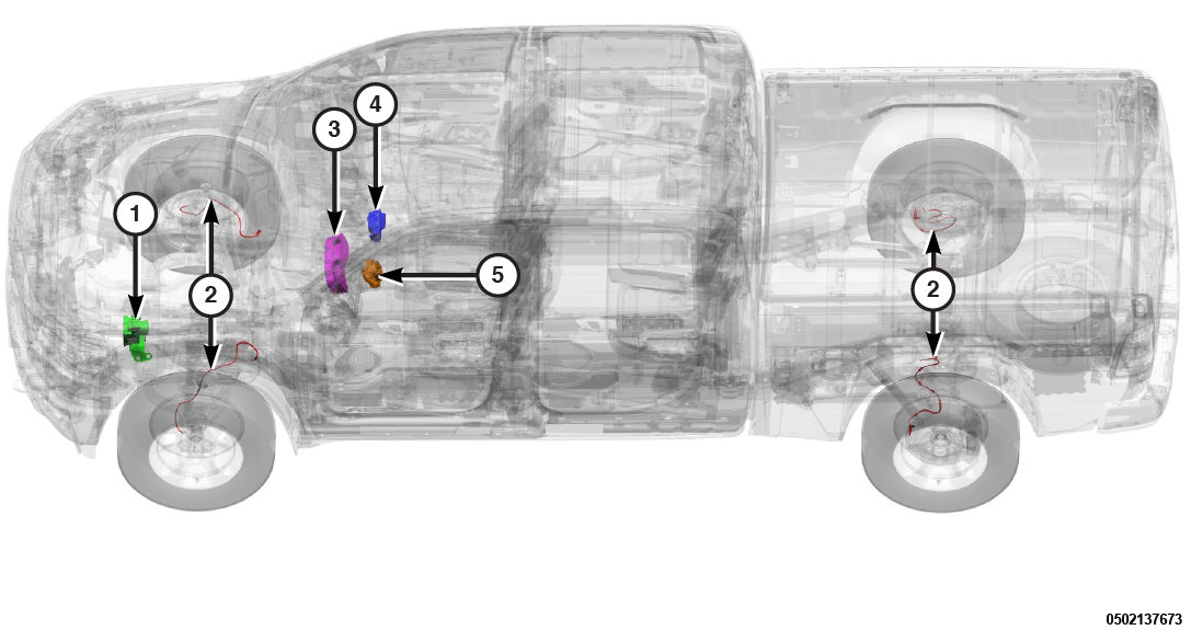 |
The Anti-Lock Brake System (ABS) includes the following components:
Component Index
|
1. |
|
|
2. |
|
|
3. |
|
|
4. |
|
|
5. |
| NOTE: |
The Electronic Stability Control (ESC) may also be referred to as Electronic Stability Program (ESP) depending on the vehicle model year and configuration. |
OPERATION
The ABS module is mounted to the Hydraulic Control Unit (HCU) together forming the Integrated Control Unit (ICU). The ABS module is a micro-controller based device which monitors the brake system during normal braking and controls it when the vehicle is in an ABS stop. The ABS function avoids wheel lock during braking maneuvers, maintaining the direction of the vehicle, and optimizing stopping distance.
The primary functions of the ABS are to:
- Monitor the ABS for proper operation.
- Detect wheel locking or wheel slipping tendencies by monitoring the speed of all four wheels of the vehicle.
- Control fluid modulation to the wheel brakes while the system is in an ABS mode.
- Store diagnostic information.
- Provide communication to the scan tool while in diagnostic mode.
- Illuminate the ABS, ESC, BRAKE, or EPB warning indicator lamp when the system is faulted.
- Illuminate ESC or Electronic Parking Brake (EPB) function lamp when a vehicle dynamic event is occurring.
- Illuminate the EPB warning lamp when a malfunction is present.
- Provide vehicle speed information, by monitoring the wheel speed sensors, to all modules on the Controller Area Network-Chassis (CAN-C) bus.
The ABS module constantly monitors the ABS for proper operation. If the ABS module detects a fault, it will turn on a warning indicator lamp and disable the ABS. The normal base braking system will remain operational.
| NOTE: |
If the vehicle is equipped with traction control, the ESC function lamp will illuminate anytime the amber ABS warning indicator lamp illuminates. |
The ABS module continuously monitors the speed of each wheel through the signals generated by the wheel speed sensors to determine if any wheel is beginning to lock. When a wheel locking tendency is detected, the ABS module commands the solenoids to actuate. The solenoids then opens and closes the valves in the HCU that modulate brake fluid pressure in some or all of the hydraulic circuits. The ABS module continues to control pressure in individual hydraulic circuits until a locking tendency is no longer present. The ABS module contains a self-diagnostic program that monitors the ABS for system faults. When a fault is detected, a warning indicator lamp is turned on and a Diagnostic Trouble Code (DTC) fault is then stored in a diagnostic program memory. A latched fault will disable certain system functionality for the current ignition cycle. An unlatched fault will disable certain system functionality until the fault condition disappears. These DTCs will remain in the ABS module memory even after the ignition has been turned off. The DTCs can be read and cleared from the ABS module memory by a technician using a scan tool. If not cleared with a scan tool, the fault occurrence and DTC will be automatically cleared from the ABS module memory after the identical fault has not been seen during the next 100 ignition cycles. Drive-off may be required for the ABS or ESC warning indicator lamp to go out on the next ignition cycle. Drive-off may be required for the amber ABS warning indicator lamp to go out on the next ignition cycle.
The ABS has multiple subsystems including, but not limited to, Traction Control System (TCS), Electric Parking Brake (EPB), Brake Assist System (BAS), Hydraulic Boost Compensation (HBC), Electronic Stability Control (ESC), Hill Start Assist (HSA), Electronic Roll Mitigation (ERM), Trailer Sway Control (TSC), and Hill Descent Control (HDC), Ready Alert Braking (RAB), Rainy Brake Support (RBS), Cornering Brake Control (CBC), Drag Torque Control [Motor Schleppmomenten Regelung] (MSR), and Off-Road ABS (ORA) ESC. All of these systems work together to enhance vehicle stability and control in various driving conditions.
A brief explanation of each subsystem follows:
ELECTRIC PARK BRAKE (EPB)
The purpose of the EPB is to replace the traditional manually operated park brake hardware in a vehicle. It replaces the traditional manually pulled lever system pulling a cable attached to the brake with an electronic switch and computer-controlled actuator fixed to the brake.
TRACTION CONTROL SYSTEM (TCS)
This system monitors the amount of wheel spin of each of the driven wheels. If wheel spin is detected, brake pressure is applied to the slipping wheel(s) to provide enhanced acceleration and stability.
BRAKE ASSIST SYSTEM (BAS)
The BAS is designed to optimize the vehicle's braking capability during emergency braking maneuvers. The system detects an emergency braking situation by sensing the rate and amount of brake application and then applies optimum pressure to the brakes.
HYDRAULIC BOOST COMPENSATION (HBC)
In the event of loss of booster vacuum, additional brake pressure will be supplied by the ESC hydraulic pump in order to restore normal braking capability. Since additional pressure is being provided by the ESC pump, small pulsations will be felt by the driver through the brake pedal.
ELECTRONIC STABILITY CONTROL (ESC)
The ESC system enhances directional control and stability of the vehicle by applying the brake of the appropriate wheel to assist in counteracting an over/under steer condition. Engine power may also be reduced to help the vehicle maintain the desired path. The ESC may use the following signals to calculate the vehicle ESC intervention:
- Vehicle speed estimation.
- Lateral acceleration.
- Longitudinal acceleration.
- Yaw rate.
- Steering angle.
- Gas Pedal Position.
- Engine Torque.
- Master Cylinder Pressure information.
HILL START ASSIST (HSA)
| NOTE: |
The HSA system does not operate on an automatic transmission vehicle in the neutral position. |
The HSA system is designed to maintain the level of brake pressure for a short period of time after the brake pedal is released so that the vehicle does not roll on a hill between releasing the brake pedal and applying the accelerator pedal. The following must be true for HSA to activate:
- The vehicle must be stopped with the brake applied.
- The vehicle must be at a eight percent or greater incline (three percent for manual transmissions).
- Gear selection must match uphill direction (forward gear for uphill, reverse for backing uphill).
ELECTRONIC ROLL MITIGATION (ERM)
The ERM feature anticipates the potential for wheel lift by monitoring the driver’s steering wheel input and the vehicle speed. When ERM determines that the rate of change of the steering wheel angle and vehicle speed are sufficient to potentially cause wheel lift, it applies the appropriate brake, and may reduce engine power, to reduce the chance that wheel lift will occur. ERM will only intervene during very severe or evasive driving maneuvers. It cannot prevent wheel lift due to other factors such as road condition, leaving the roadway, striking objects or other vehicles.
TRAILER SWAY CONTROL (TSC)
TSC detects when a vehicle/trailer combination starts oscillating as the trailer will cause yaw oscillation of the towing vehicle (ESP sensors). There are no supplementary sensors on the trailer or trailer coupling device. This means that TSC is essentially a stabilizing device (damping) for the towing vehicle. When an oscillation motion has been detected, the vehicle/trailer combination is stabilized by means of alternate brake pressure build-up on the front axle, and on the rear axle as necessary. In addition to this pressure build-up, the vehicle is decelerated by means of a superimposed brake pressure build-up on all wheels. If further swinging is detected, the deceleration intervention is increased. The deceleration intervention is accompanied by a reduction in engine torque. In order to reduce the oscillation motion of the towing vehicle, two things happen. The brake pressure is built up alternately on the front axle (and optionally on the rear axle as well), and is synchronized with the vibration characteristics. This is accompanied by superimposed, regulated deceleration on all wheels. For this purpose, the engine torque is reduced to a minimum level of zero torque in order to prevent the "Engine versus brake" situation from arising. The maximum drag torque may also be used. If the driver himself corrects the steering in order to stabilize the vehicle when the oscillation motion starts, the TSC may not reach the activation threshold. If the driver raises the speed again to the critical level after the TSC has intervened, the TSC will intervene again when the critical level has been detected. It is not possible to limit the vehicle speed after the stability limit of the vehicle/trailer combination has been detected. Cruise Control, Adaptive Cruise Control (ACC) and ACC Stop will be cancelled if TSC is active.
HILL DESCENT CONTROL (HDC) — N/A on 4 x 2 models
HDC is a low-speed limiter which allows the driver to concentrate on the path of the vehicle while negotiating off-road downhill grade of sufficient magnitude. HDC will apply hydraulic braking without requiring the driver to apply the brake pedal. HDC activates the front and rear brakes while descending a hill to limit vehicle speed to a pre-set value. Descent speed is selectable (when the gear shifter is in the drive position) via the transmission gear +/- selectors. HDC is armed by a switch, but the ESC will not actively control braking unless the conditions are met to activate the feature. For more operating information see the Owner’s Manual.
Conditions for enabling HDC are:
- There are no ESC faults.
- There are no Transmission Control Module (TCM) faults.
- Ignition in the Run position.
- Driver door must be closed.
- The driveline is in 4Low.
- The driver pushes the HDC switch.
- Parking brake is not engaged.
- The vehicle speed is below the entry threshold.
| NOTE: |
The gear shift selector may be in any position (P, R, N, D, or any numeric indicated value). |
| NOTE: |
If the driver attempts to enable the feature and one or more of the conditions above are not met the ESC shall "BLINK" for 5 seconds. |
HILL START ASSIST (HSA) — N/A on 4 x 2 models
The Hill Holder feature referred to as the Hill Start Assist feature of the ESC system. The function shall help the driver during the drive-off maneuver on a slope maintaining and releasing the brake pressure allowing a comfortable maneuver. HSA shall only become available during a drive off condition, that is HSA functionality will only activate after the system determines that the vehicle has first completely stopped. HSA shall determine the minimum hydraulic pressure to keep the vehicle at a standstill and maintain that pressure for a calibratable time after the driver stops pressing brake pedal. HSA shall determine the minimum engine torque required to accelerate the vehicle smoothly during the beginning of a drive off maneuver. HSA shall only activate while the vehicle is on a slope, the grade of which is calibratable. While the HSA feature is holding hydraulic pressure the brake lamps shall be lit. The only interaction the customer has with the feature is through a configuration screen. For more details relating to the customer configuration see the Owner’s Manual.
READY ALERT BRAKING (RAB)
The RAB function reduces the air gap between discs and pads and/or sensitizes Hydraulic Brake Assist (HBA) entry criteria to make it easier to enter HBA for braking maneuvers after a fast gas pedal release.
RAINY BRAKE SUPPORT (RBS)
The RBS function, also called disc wiping, supports braking performance under wet conditions. By cyclically applying the brake lining, the pressure build-up time for the brake is reduced. After enable conditions are met, the dry braking is applied whereby the brakes on the front and/or both axles are activated for a limited time with a very low brake pressure, not perceivable to the driver. The pressure is gently increased and reduced again. The dry brake function is deactivated through EEPROM and turned on again if need be.
CORNERING BRAKE CONTROL
The CBC function reduces the over steer tendency of the vehicle during an ABS braking maneuver in a curve by providing an anti-yaw moment through reduction of front inner wheel pressure. CBC is active during braking in curve maneuvers or when ABS function is active. CBC is not active when ABS function is not active. The ABS module will also monitor torque steering disturbance during CBC activation.
DRAG TORQUE CONTROL [MOTOR SCHLEPPMOMENTEN REGELUNG]
The MSR function tries to avoid locking of the driving axle during throttle-off maneuvers due to engine braking torque. MSR is active during throttle-off maneuvers. MSR activates when the locking tendency of a driving wheel exceeds the target value.
OFF-ROAD ABS (ORA) ESC
On deformable surfaces (gravel, sand, etc), a specific ORA calibration with higher wheel slip targets may be used to improve the ABS stopping distance. A larger wheel slip will help take advantage of the wedge effect of the deformable surface in front of the tires. ORA shall be automatically enabled if the vehicle has terrain switch setting(s) for deformable surfaces, or it may be enabled if the transfer case is switched to low range. The ORA logic may also be used if the ESC detects a deformable surface based on information from the wheel speed sensors, longitudinal acceleration sensor, and brake torque model. The larger wheel slip specifications used in ORA are dependent on vehicle speed, steering wheel angle, and surface roughness estimation. The ORA logic is not intended to be used on dry or wet asphalt, packed snow, or ice.
Electronic Stability Program (ESP) Switch
The ESP switch is located in the switch bank pod. When the ESP switch is depressed, the switch bank pod sends a Controller Area Network-Interior High Speed (CAN-IHS) signal to the BCM. The BCM then gates a CAN-C signal to the ABS module.
Instrument Panel Cluster (IPC)
The IPC for this vehicle is located in the instrument panel above the steering column opening. The IPC gauges and indicators are visible through an opening in the cluster bezel and are protected by a clear plastic cluster lens that is secured to the cluster housing by integral latch formations. Several versions of the IPC are offered on this vehicle. These versions accommodate all of the variations of optional equipment and regulatory requirements for the various markets in which the vehicle is offered. The IPC utilizes integrated circuitry and information carried on the CAN-C and CAN-IHS along with several hard wired inputs to monitor other sensors and switches in the vehicle. In response to those inputs, the internal circuitry and programming of the IPC allow it to monitor many electronic functions and features of the vehicle.
The IPC receives the following:
CAN-C Inputs
- ABS warning lamp ON request.
- ESC warning lamp ON request.
- ESC OFF lamp ON request.
- BRAKE warning lamp ON request.
- EPB warning lamp ON request.
- Key in ignition status.
- Commanded ignition switch status.
Integrated Control Unit (ICU)
The ICU is located in the left rear corner of the engine compartment near the brake master cylinder. The ABS module is fused by the Power Distribution Center (PDC). The ICU consists of a valve body, pump motor, low pressure accumulators, inlet valves, outlet valves and noise attenuators, and the ABS module. Accumulators in the valve body store extra fluid released from the calipers during ABS mode operation. The pump is used to clear the accumulator of brake fluid and is operated by a DC type motor. The motor is controlled by the ABS module. The valves modulate brake pressure during anti-lock braking and are controlled by the ABS module. The HCU provides individual pressure control to each front and rear brake. During anti-lock braking, the solenoid valves are opened and closed as needed. They are cycled rapidly and continuously to modulate pressure and control wheel slip and deceleration. Brake Traction Control and Electronic Stability Program modulate pressure on each wheel individually without any driver brake input. During normal braking, the HCU solenoid valves and pump are not activated. The master cylinder and power booster operate the same as a vehicle without an ABS brake system. The valves are all contained in the valve body portion of the HCU.
During anti-lock braking, solenoid valve pressure modulation occurs in three stages; pressure increase, pressure hold, and pressure decrease. A brief description of each pressure modulation is as follows:
PRESSURE INCREASE
- The inlet valve is open and the outlet valve is closed during the pressure increase cycle. The pressure increase cycle is used to reapply the brakes. This cycle controls re-application of fluid apply pressure.
PRESSURE HOLD
- Both solenoid valves are closed in the pressure hold cycle but only the inlet valve is energized. Fluid apply pressure in the control channel is maintained at a constant rate. The ABS module maintains the hold cycle until sensor inputs indicate a pressure change is necessary.
PRESSURE DECREASE
- The outlet valve is opened and the inlet valve is closed during the pressure decrease cycle. A pressure decrease cycle is initiated when speed sensor signals indicate high wheel slip at one or more wheels. At this point, the ABS module closes the inlet then opens the outlet valve, which also opens the return circuit to the accumulators. Fluid pressure is allowed to bleed off (decrease) as needed to prevent wheel lock. Once the period of high wheel slip has ended, the ABS module closes the outlet valve and begins a pressure increase or hold cycle as needed.
The ABS receives the following:
CAN-C Inputs
- Transfer case status.
- Accelerator pedal position (Calculated).
- Static engine torque / Effective engine torque.
- Steering wheel angle.
- Commanded ignition switch status.
- Vehicle speed.
The ABS provides the following:
CAN-C Outputs
- ABS warning lamp ON request.
- ESC warning lamp ON request.
- ESC OFF lamp ON request.
- BRAKE warning lamp ON request.
- EPB warning lamp ON request.
- Status of any ABS brake event.
Steering Column Control Module (SCCM)
The SCCM is located near the top of the steering column below the steering wheel. The SCCM includes the Steering Angle Sensor (SAS), the clockspring, lighting multifunction switch, and wiper multifunction switch. The SCCM is secured to the steering column by an integral band clamp on the bottom of the instrument panel side of the SCCM. The SCCM has a centering attachment screw located on the top of the instrument panel side of the SCCM to be certain the SCCM is centered properly on the steering column.
The SCCM provides the following CAN-C Output — Steering wheel angle.
Wheel Speed Sensors (WSS)
A WSS is used at each of the four wheels. The front sensors are mounted to the front bearing assembly. The rear sensors are mounted to the rear axle shaft mounting flange. The gear type tone wheel is mounted to the outboard ends of the axle shafts and serves as the trigger mechanism for each rear sensor. The front tone rings are incorporated into the front wheel bearing assembly. The sensors convert wheel speed into small digital current signals in amperage. The ABS sends 12 volts to the sensors. The sensor is typically comprised of either a hall effect or a magneto-resistive element integrated with signal conditioning circuit. The sensor produces signals alternating between two constant levels with frequency proportional to the associated wheel speed. The sensor reads either a toothed ferrous tone wheel or a magnetically charged encoder for signal generation and that signal is sent to ABS module.
The WSS provides the following CAN-C Output — RPM for each wheel.