Removal And Installation
SENSOR, Vacuum Pressure
▸Contents: 05 - Brakes
05 - Brakes, ABS
- Description and OperationAnti-Lock Brake System (Abs)
- Standard ProcedureStandard Procedure - Antilock Brake System Bleeding
- Technical SpecificationsTorque Specifications
Electrical
SENSOR, Wheel Speed, Front
SENSOR, Wheel Speed, Rear
SWITCH, Electronic Stability Program (ESP)
Hydraulic/Mechanical
Integrated Control Unit (Icu)
Removal and Installation
Hydraulic Control Unit (Hcu)
Removal and Installation
05 - Brakes, Base
- Warning
- Caution
- DescriptionBase Brake System
- Diagnosis And Testing
- Standard ProcedureBrake System Bleeding
- Special Tools
Technical Specifications
Electrical
SWITCH, Brake Fluid Level
Removal and Installation
SWITCH, Adjustable Pedals
PUMP, Electric Vacuum
- SENSOR, Vacuum PressureRemoval And Installation
Hydraulic/Mechanical
ADAPTER, Disc Brake Caliper
Removal and Installation
CALIPER, Disc Brake, Front
CALIPER, Disc Brake, Rear
MASTER CYLINDER, Brake
PADS, Brake, Front
PADS, Brake, Rear
PEDAL(S), Brake and/or Accelerator
ROTOR, Brake
- Diagnosis and TestingDiagnosis And Testing - Disc Brake Rotor
Removal and Installation
Parking Brake
- Description And Operation
ACTUATOR, Electric Park Brake
SWITCH, Electric Park Brake
REMOVAL
| NOTE: |
5.7L shown, all other similar. |
- Remove the engine cover .
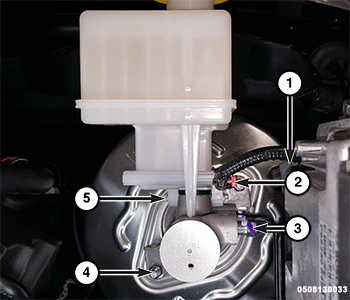
- Disconnect the vacuum pressure sensor wire harness connector.
1 - Vacuum Pressure Sensor Wire Harness Connector 2 - Brake Fluid Switch Wire Harness Connector 3 - Master Cylinder Brake Line Flare Nuts 4 - Master Cylinder Nuts 5 - Brake Fluid Reservoir Bolts - Remove the vacuum pressure sensor from the brake booster.
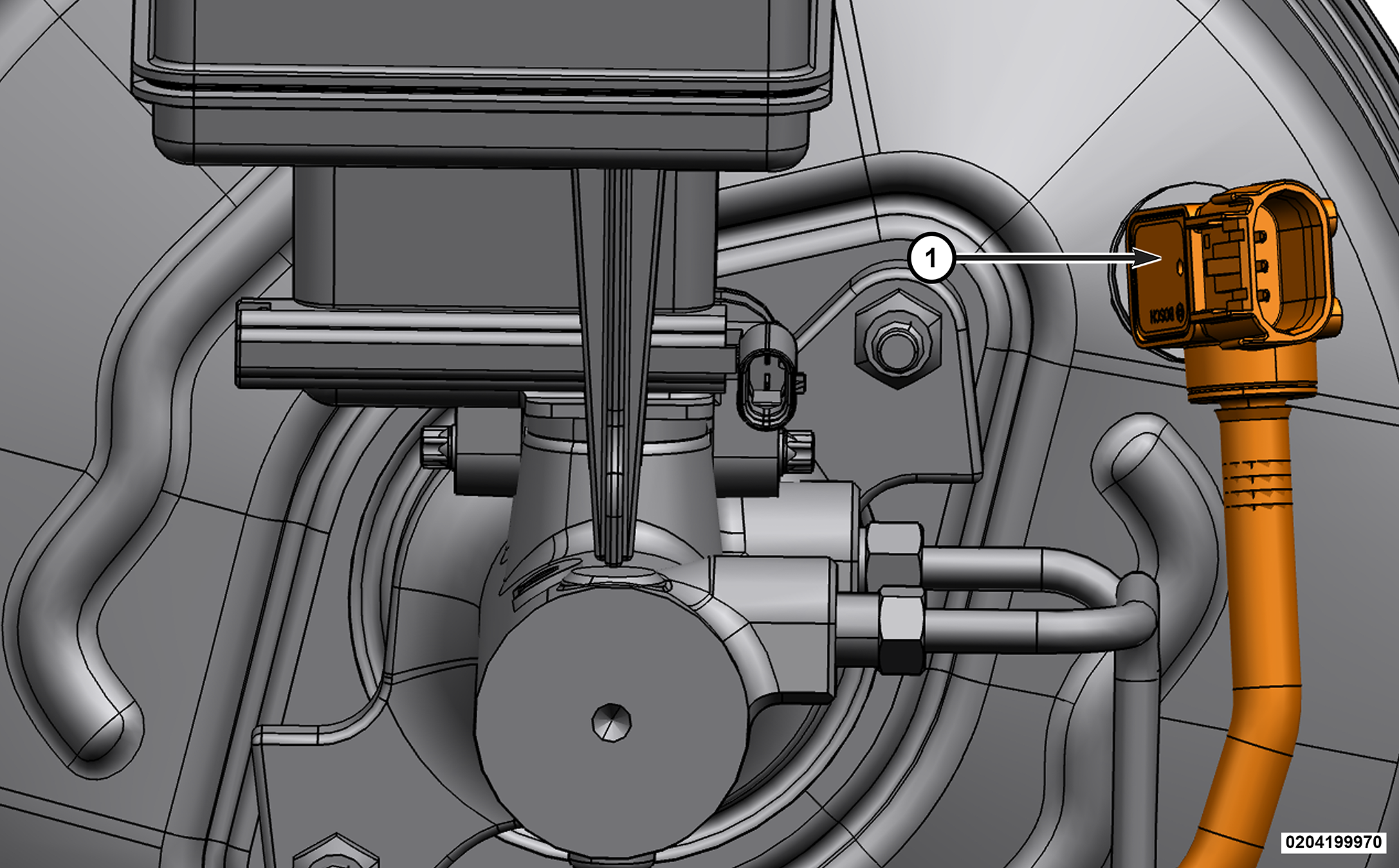
1 - Vacuum Pressure Sensor - Release the locking tabs and disengage the vacuum line from the electric vacuum pump.
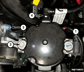
1 - Electric Vacuum Pump Wire Harness Connector 2 - Vacuum Pump Bolts 3 - Vacuum Pump Bracket Bolts 4 - Vacuum Line - Disconnect the vacuum line from the intake manifold.
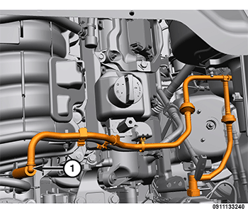
1 - Vacuum Line - Disengage the vacuum line from the routing clips.
- Remove the vacuum pressure sensor and vacuum line assembly.
INSTALLATION
| NOTE: |
5.7L shown, all other similar. |
- Position the vacuum pressure sensor and vacuum line assembly to the vehicle.
- Connect the vacuum line to the intake manifold.
1 - Vacuum Line - Secure the vacuum line routing clips.
- Connect the vacuum line to the electric vacuum pump.
1 - Electric Vacuum Pump Wire Harness Connector 2 - Vacuum Pump Bolts 3 - Vacuum Pump Bracket Bolts 4 - Vacuum Line - Install the vacuum pressure sensor to the brake booster.
1 - Vacuum Pressure Sensor - Connect the vacuum pressure sensor wire harness connector.
1 - Vacuum Pressure Sensor Wire Harness Connector 2 - Brake Fluid Switch Wire Harness Connector 3 - Master Cylinder Brake Line Flare Nuts 4 - Master Cylinder Nuts 5 - Brake Fluid Reservoir Bolts - Install the engine cover .