Removal and Installation
Ring And Pinion Gear - Rba260
▸Contents: 03 - Differential and Driveline
Description and Operation
Diagnosis and Testing
ASSEMBLY, Differential
Disassembly and Assembly
Actuator/Motor
GEAR, Ring and Pinion
Removal and Installation
Joints
SHAFTS, Axle/Drive/Half
Valves
Removal and Installation
REMOVAL
| NOTE: |
The ring gear and pinion are serviced in a matched set. Never replace one gear without replacing the other matching gear. |
- Remove the differential from the differential housing (Refer to 03 - Differential and Driveline/ASSEMBLY, Differential/Removal and Installation) .
- Place the differential case in a vise with soft metal jaw protectors.
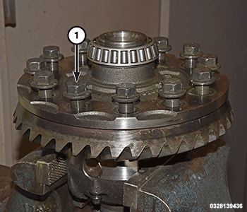
- Remove the ring gear bolts from the differential case and DISCARD .
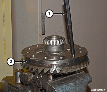
1 – Ring Gear Bolts - Drive the ring gear off the differential case using a drift punch or soft hammer.
NOTE: If using a drift punch, take care not to hit the threads on the ring gear or damage may occur.
1 – Drift Punch 2 – Ring Gear - Install the bolts into two of the threaded holes in the pinion flange 180° apart.
- Position Holder, Yoke 6719A against the pinion flange and install a bolt and washer into one of the remaining threaded holes. Tighten the bolts so the yoke holder is held to the flange.
- Remove and DISCARD the pinion flange nut.
- Place an alignment mark on the pinion flange to pinion shaft.
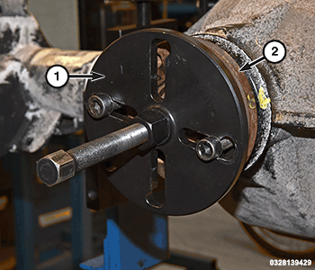
- Remove the pinion flange using Puller, Companion Flange C-452 .
1 – Puller, pinion Flange C-452 2 – pinion Flange - Remove pinion gear from the housing with Pinion Driver 2088500030 .
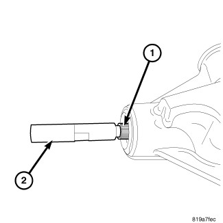
1 – Pinion Gear 2 – Pinion Driver 2088500030 - Remove the pinion seal using a suitable tool.
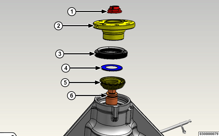
1 - Pinion nut 4 - Oil Slinger 2 - Pinion Flange 5 - Pinion Bearing 3 - Pinion Seal 6 - Pinion Gear - Remove the front pinion bearing and oil slinger.
- Remove the front pinion bearing cup using a drift punch.
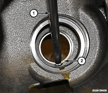
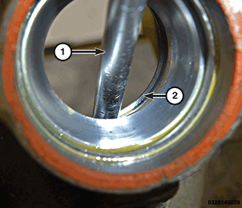
1 – Drift Punch 2 – Front Pinion Bearing Cup - Remove the rear pinion bearing cup from the housing using a drift punch.
1 – Drift Punch 2 – Rear Pinion Bearing Cup - Remove the collapsible spacer from the pinion shaft.
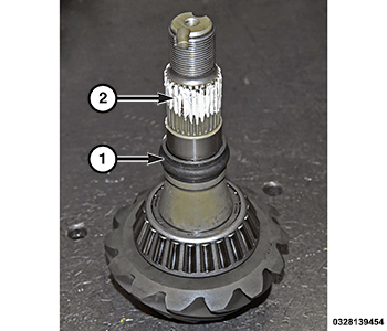
1 – Collapsible Spacer 2 – Pinion Shaft - Remove the rear pinion bearing from the pinion shaft using bearing separator and a press or using Puller Press, Carrier Bearing 2022100030 , C-293-PA-1A Slotted Bar and Blocks, Pinion Head Bearing 2088400030 .
INSTALLATION
| NOTE: |
The ring gear and pinion gear are serviced as a matched set. Do not replace one gear without replacing the other matched gear. If the ring and pinion gears or bearings are replaced refer to (Refer to 03 - Differential and Driveline/Adjustments) for Pinion Gear Depth Setting. Do not reuse the bearings. |
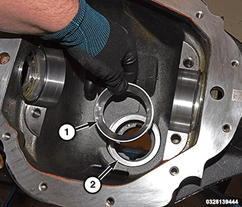
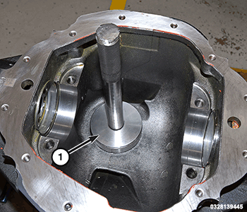
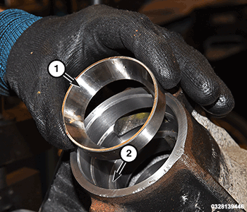
- Install a NEW rear pinion bearing cup.
1 – Rear Pinion Bearing Cup 2 – Pinion Bearing Cup Bore - Using Installer, Pinion Head Brg Race RB260 2088700030 and Driver Handle, Universal C-4171 . fully seat the bearing cup in the pinion housing.
1 – Installer, Bearing 2088700030 With Driver Handle, Universal C-4171 - Install a NEW front pinion bearing cup.
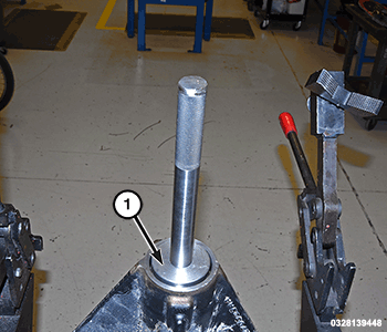
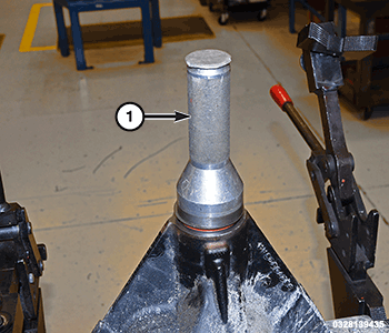
1 – Front Pinion Bearing Cup 2 – Front Pinion Bearing Cup Bore - Using Installer, Pinion Tail Brg Race RB260 2088800030 and Driver Handle, Universal C-4171 , fully seat the bearing cup in the pinion housing.
1 – Installer, Bearing Cup 2088800030 With Driver Handle, Universal C-4171 - Install a NEW front pinion bearing into the housing.
1 - Pinion nut 4 - Oil Slinger 2 - Pinion Flange 5 - Pinion Bearing 3 - Pinion Seal 6 - Pinion Gear - Install the oil slinger.
- Install a NEW seal using Installer, Seal 2089000030 .
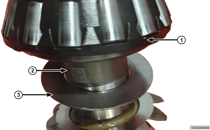
1 – Installer, Seal 2089000030 - Install the selected pinion depth shim onto the pinion shaft.
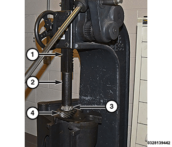
1 - Pinion Bearing 2 - Pinion Shaft 3 - Pinion Depth Shim - Install the NEW rear bearing on the pinion gear using Installer, Bearing 6446 and a press.
1 – Press 2 – Installer, Bearing 6446 3 – Rear Pinion Bearing 4 – Pinion Gear - Install a NEW collapsible spacer on the pinion shaft and apply Mopar® Thread Sealant to splines of the splines of the pinion shaft.
1 – Collapsible Spacer 2 – Mopar® Thread Sealant - Align the marks on the pinion shaft and the pinion flange and install using Installer, Pinion Flange 2088600030 and Holder, Yoke 6719A .
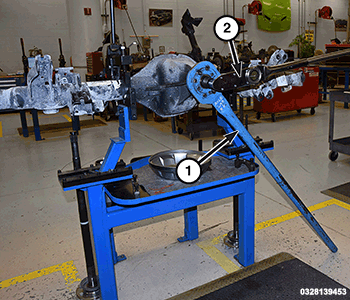
- Install a NEW pinion nut.
1 – Torque Wrench 2 – Holder, Yoke - Hold the pinion flange using Holder, Yoke 6719A and tighten the pinion nut.
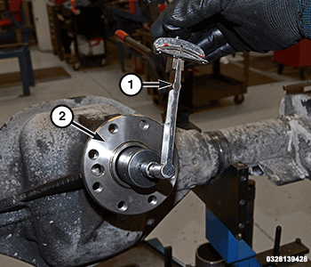
- Rotate the pinion flange several times to seat the pinion bearings.
1 – Inch Pound Torque Wrench 2 – Pinion Flange - Measure Pinion Torque To Rotate (PTTR) using an inch pound torque wrench. Measure PTTR frequently to avoid over-crushing the collapsible spacer. Pinion Torque To Rotate is:
- New Bearings: 0.5 - 3.1 N·m (4 - 27 in. lbs.)
NOTE: If the PTTR is low, tighten the pinion nut in 6.8 N·m (5 ft. lbs.) increments until the PTTR is achieved.
NOTE: Once proper PTTR is achieved, the pinion nut must be staked to the pinion to prevent pinion nut movement.
CAUTION: Never loosen pinion nut to decrease pinion bearing rotating torque. If pinion torque to rotating is exceeded a new collapsible spacer must be installed. Failure to follow these instruction will damage the axle.
- New Bearings: 0.5 - 3.1 N·m (4 - 27 in. lbs.)
- Position the ring gear on the differential case and start two NEW ring gear bolts. This will provide case-to-ring gear bolt hole alignment.
1 – Ring Gear Bolts - Invert the differential case in the vise.
- Install NEW ring gear bolts and alternately tighten.
CAUTION: Never reuse the ring gear bolts. Failure to follow these instruction will result in damage.
- Install the differential case in the housing (Refer to 03 - Differential and Driveline/ASSEMBLY, Differential/Removal and Installation) .
- Verify that gear mesh, backlash and contact patterns are within the proper specifications (Refer to 03 - Differential and Driveline/Adjustments) .
- Remove the support and lower the vehicle.
 TORQUE SPECIFICATIONS - RBA260 INTERNAL