Removal and Installation
Differential Assembly - Rba260 - Limited Slip
▸Contents: 03 - Differential and Driveline
Description and Operation
Diagnosis and Testing
ASSEMBLY, Differential
Disassembly and Assembly
Actuator/Motor
GEAR, Ring and Pinion
Removal and Installation
Joints
SHAFTS, Axle/Drive/Half
Valves
Removal and Installation
REMOVAL
- Raise and support the vehicle (Refer to 04 - Vehicle Quick Reference/Hoisting/Standard Procedure) .
- Remove the fill and drain plugs from the differential housing.
- Remove the differential cover (Refer to 03 - Differential and Driveline/COVER/Removal and Installation) .
- Clean the housing cavity with brake cleaner and a lint free cloth.
NOTE: Do not use steam, kerosene or gasoline to clean the housing.
- Remove the axle shafts (Refer to 03 - Differential and Driveline/SHAFTS, Axle/Drive/Half/Removal and Installation) .
NOTE: Side play resulting from bearing races being loose on case hubs requires replacement of the differential case.
- Mark the differential housing and bearing caps for installation reference.
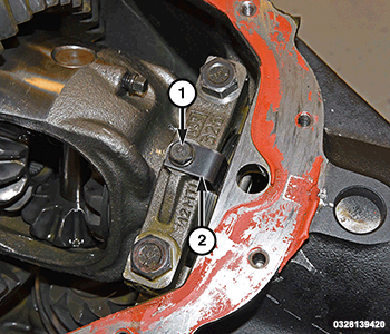
- Remove the adjuster lock bolt and remove the adjuster lock tab.
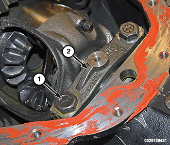
1 – Adjuster Lock Bolt 2 – Adjuster Lock Tab - Loosen the differential bearing cap bolts.
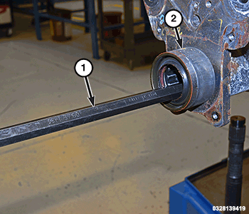
1 – Differential Bearing Cap Bolts 2 – Differential Bearing Cap - Loosen the differential bearing adjusters through the axle tubes using Wrench, Differential Preload C-4164 .
1 – Wrench, Differential Preload C-4164 2 – Axle Tube - Hold the differential case while removing the bearing caps.
NOTE: Tag the differential bearing cups and the threaded adjusters after removal to indicate their location.
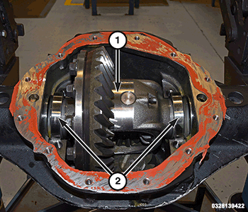
1 – Differential Case 2 – Bearing Cups - Remove the differential case and bearing cups.
INSTALLATION
- Apply a coating of hypoid gear lubricant to the differential bearings and bearing cups.
- Install the differential case with the bearing cups into the housing.
1 – Differential Case 2 – Bearing Cups - Install the differential bearing caps in their original locations.
1 – Differential Bearing Cap Bolts 2 – Differential Bearing Cap - Install bearing cap bolts and tighten the upper bolts to 14 N⋅m (10 ft. lbs.). Tighten the lower bolts finger-tight until the bolt head is seated. Perform the differential bearing preload and adjustment procedure (Refer to 03 - Differential and Driveline/Adjustments) .
NOTE: Verify that all of the bearing cap bolts are tightened to the proper (Torque Specifications) before proceeding.
- Install the axle shafts (Refer to 03 - Differential and Driveline/SHAFTS, Axle/Drive/Half/Removal and Installation) .
- Install the differential cover (Refer to 03 - Differential and Driveline/COVER/Removal and Installation) .
- Fill the differential with lubricant to the proper specification (Refer to 04 - Vehicle Quick Reference/Capacities and Recommended Fluids - Specifications) .
- Remove the support and lower the vehicle.
| NOTE: |
Limited Slip Differential (LSD) equipped vehicles should be road tested by making 10 to 12 slow figure-eight turns. This maneuver will pump the lubricant through the clutch discs to eliminate a possible chatter noise complaint. |