Removal and Installation
Axle Shaft - Rba260
▸Contents: 03 - Differential and Driveline
Description and Operation
Diagnosis and Testing
ASSEMBLY, Differential
Disassembly and Assembly
Actuator/Motor
GEAR, Ring and Pinion
Removal and Installation
Joints
SHAFTS, Axle/Drive/Half
Valves
Removal and Installation
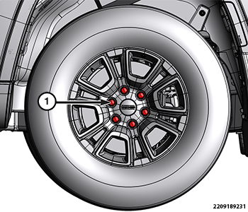
- Raise and support the vehicle (Refer to 04 - Vehicle Quick Reference/Hoisting/Standard Procedure) .
- Remove the brake caliper, adapter and rotor (Refer to 05 - Brakes, Base/Hydraulic/Mechanical/ROTOR, Brake/Removal and Installation) .
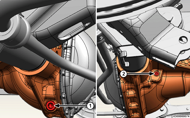
- Remove the drain plug and drain the fluid.
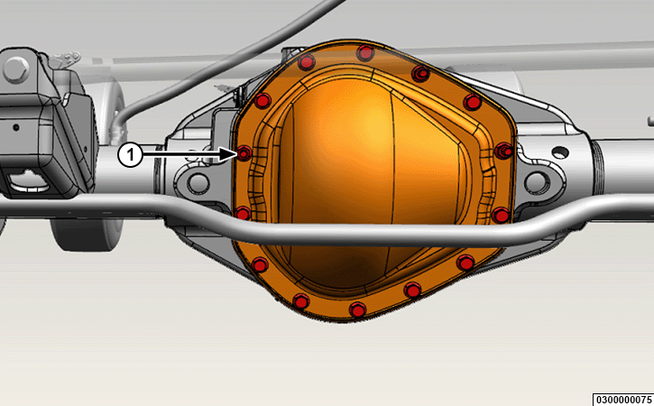
- Remove the differential cover (Refer to 03 - Differential and Driveline/COVER/Removal and Installation) .
- Install the differential drain plug.
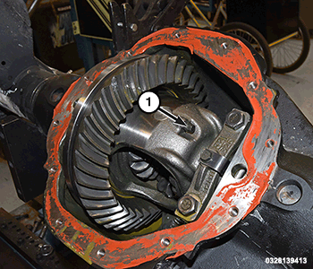
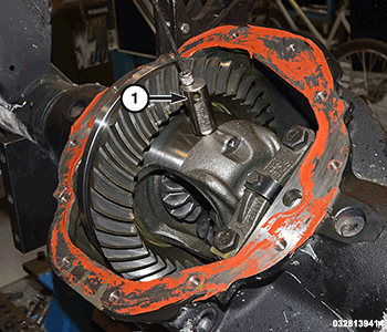
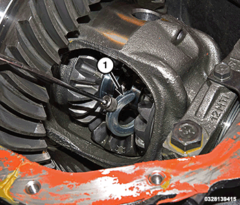
- Rotate the differential case so the pinion mate shaft lock screw is accessible. Remove the lock screw and DISCARD .
1 – Pinion Mate Shaft Lock Screw - Remove the pinion mate shaft from the differential case.
1 – Pinion Mate Shaft - Push axle shaft inward and remove the C-lock from the axle shaft.
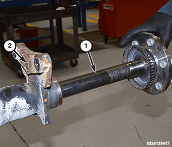
1 – C-Lock - Remove the axle shaft carefully to prevent damage to the shaft bearing and seal in the axle.
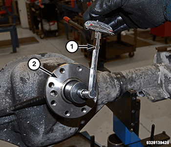
1 – Axle Shaft 2 – Axle
INSTALLATION
Follow the removal procedure in reverse for general reassembly of the components on the vehicle. The steps listed below are calling out specific procedures that should be followed during installation.
- Lubricate bearing bore and seal lip with gear lubricant.
- Use care to prevent the axle shaft splines from damaging axle shaft seal when installing the shaft.
- Install a NEW pinion mate shaft lock screw using Loctite® on the threads.
- Fill the differential to the specified level using the specified fluid (Refer to 04 - Vehicle Quick Reference/Capacities and Recommended Fluids/Specifications) .
 TORQUE SPECIFICATIONS - RBA260 INTERNAL