Description and Operation
Rear Axles - C235 And Rba260
▸Contents: 03 - Differential and Driveline
Description and Operation
Diagnosis and Testing
ASSEMBLY, Differential
Disassembly and Assembly
Actuator/Motor
GEAR, Ring and Pinion
Removal and Installation
Joints
SHAFTS, Axle/Drive/Half
Valves
Removal and Installation
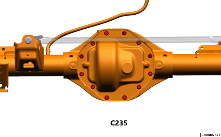 |
DESCRIPTION - C235
The C235 rear axle housing has a cast iron center section with steel axle tubes. The housing contains the differential, ring and pinion gears, the axle shafts and associated bearing and seals.
The rear axle is mounted in the vehicle via the rear suspension, and is affixed via the rear shock absorbers and the rear upper and lower control arms. A track bar is mounted behind the rear axle and is position laterally between the axle housing and the frame. The track bar has rubber/urethane bushings at each end. The track bar keeps the rear axle centered in relation to the vehicles frame.
An optional thermal rear axle is available which uses engine coolant to bring the rear axle fluid to operating temperature more quickly to increase efficiency. The thermal axle option is only available with Rear Wheel Drive (RWD models only. This axle can be easily identified as it will have a unique differential cover that has two coolant hoses plumbed to it.
The C235 rear axle is available with three differential options:
- An open differential that provides basic differential operation to allow for differing wheel speeds when negotiating turns.
- A Limited Slip Differential (LSD) that allows differing wheel speeds when negotiating turns, but also allows torque to be biased to the wheel with the most available traction in low traction environments. This is accomplished with a set of clutches and plates between the differential pinion gears and the differential case which act as brake, creating a calculated amount of resistance to allow the wheels to turn at differing speeds.
- An electronic locking differential, which when engaged, locks the rear axles together, eliminating any allowance for differing wheel speeds. When the electronic locker is disengaged, the differential will allow for different wheel speeds when negotiating a turn. The Electronic locking differential is turned on and off by the operator with a switch in the cab. The system defaults to off when the key is cycled.
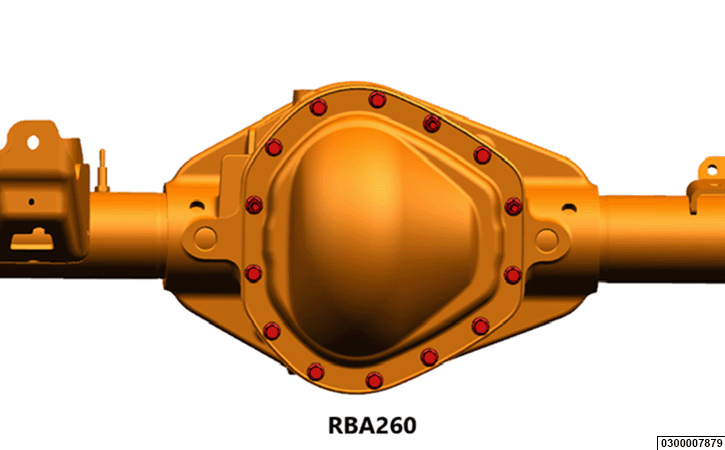 |
DESCRIPTION - RBA260
The RBA260 rear axle housing has a cast iron center section with steel axle tubes. The housing contains the differential, ring and pinion gears, the axle shafts and associated bearing and seals.
The rear axle is mounted in the vehicle via the rear suspension, and is affixed via the rear shock absorbers and the rear upper and lower control arms. A track bar is mounted behind the rear axle and is position laterally between the axle housing and the frame. The track bar has rubber/urethane bushings at each end. The track bar keeps the rear axle centered in relation to the vehicles frame.
The RBA260 rear axle is available with two differential options:
- A Limited Slip Differential (LSD) that allows differing wheel speeds when negotiating turns, but also allows torque to be biased to the wheel with the most available traction in low traction environments. This is accomplished with a set of clutches and plates between the differential pinion gears and the differential case which act as brake, creating a calculated amount of resistance to allow the wheels to turn at differing speeds.
- An electronic locking differential, which when engaged, locks the rear axles together, eliminating any allowance for differing wheel speeds. When the electronic locker is disengaged, the differential will allow for different wheel speeds when negotiating a turn. The Electronic locking differential is turned on and off by the operator with a switch in the cab. The system defaults to off when the key is cycled.
OPERATION
Torque is provided to the axle form the powertrain to the pinion gear via the driveshaft. The pinion gear is supported by two tapered bearings and drives the ring gear, which is bolted to the differential case. The differential case is also supported by two tapered bearings. Within the differential case, there are two differential pinion gears and two side gears which are in constant mesh. When the differential case is being driven, the two differential pinion gears are turning because they are mounted on a shaft that is anchored to the differential case. The two pinion gears then transfer torque to the two side gears, which are splined to the axle shafts. When traveling in a straight line, with no variation in rear wheel speed, the differential pinion gears are turning with the differential case, but not spinning on the pinion shaft. Because the differential pinion gears are not spinning on the shaft, they transfer torque equally to both axles.
- When a wheel speed difference exists with an open differential:
- When negotiating a turn the wheel on the inside of the turn rotates at a slower speed than the wheel on the outside of a turn. The wheel speed difference causes the pinion gears to rotate around the pinion shaft and transfers more torque to the wheel on the outside of the turn. This allows the wheels to turn at different speeds smoothly. The wheel speed difference increases with the sharpness of the turn, the tighter the turn, the faster the pinion gears will rotate.
- When operating in a straight line in a low traction environment with one wheel having less traction than the other wheel, the differential functions much the same was when the vehicle is in a turn. In this situation, the wheel speed difference will cause the pinion gears to rotate, transferring more torque to the wheel with the least amount of traction. This is a normal characteristic of an open differential which is not desirable in many low traction environments.
- When a wheel speed difference exists with a limited slip differential:
- When negotiating a turn on a hard surface, the wheel on the inside of the turn must turn at a slower speed than the wheel on the outside of the turn. The limited slip differential will resist the speed difference, but allow the speed difference once the braking action of the limited slip clutches is overcome. Once this is achieved, the differential pinion gears will rotate, allowing less torque to reach the slower rotating wheel.
- When negotiating a turn on a limited traction surface, the wheel on the inside of the turn may spin or “slip”, due to the low traction surface not allowing the braking action of the differential pinions to be overcome.
- When operating in a straight line in a low traction environment with one wheel having less traction than the other wheel, the braking action of the clutches resist allowing the differential pinion gears to spin around the pinion shaft, allowing more torque to be available to the wheel that has greater amount of traction.
- The Limited Slip Differential is a non-preload design, this provides optimal fuel efficiency while still maintaining improved traction performance. The Limited Slip Differential operates as a torque sensing device because when torque is applied to the differential gear set the reaction forces of the bevel gears apply an axial force into the clutch system providing the torque bias. When the input torque is very low the reaction forces will decrease allowing the differential to act similar to an open differential (zero preload). Under normal operation the differential gears can be turned by hand.
- When a condition exists that should induce a wheel speed difference with Electric Locking Differential:
- When negotiating a turn on a hard surface, the electronic locking differential, when engaged, will not allow a wheel speed difference to exist. This will cause an unstable operating condition, as both rear wheels will have the same amount of torque to be available at all times. This will cause the wheel on the inside of the turn to want to spin or “slip”, and cause the vehicle to resist turning. The electronic locking differential should NOT be engaged when operating on the road in almost all cases.
- When negotiating a turn on a limited traction surface, the wheel on the inside of the turn will spin or “slip”, due to the low traction surface. If the traction varies, the more traction that is available, the more the vehicle will resist turning.
- When operating in a straight line in a low traction environment the electronic locking differential always transmits equal torque to both rear wheels when engaged.
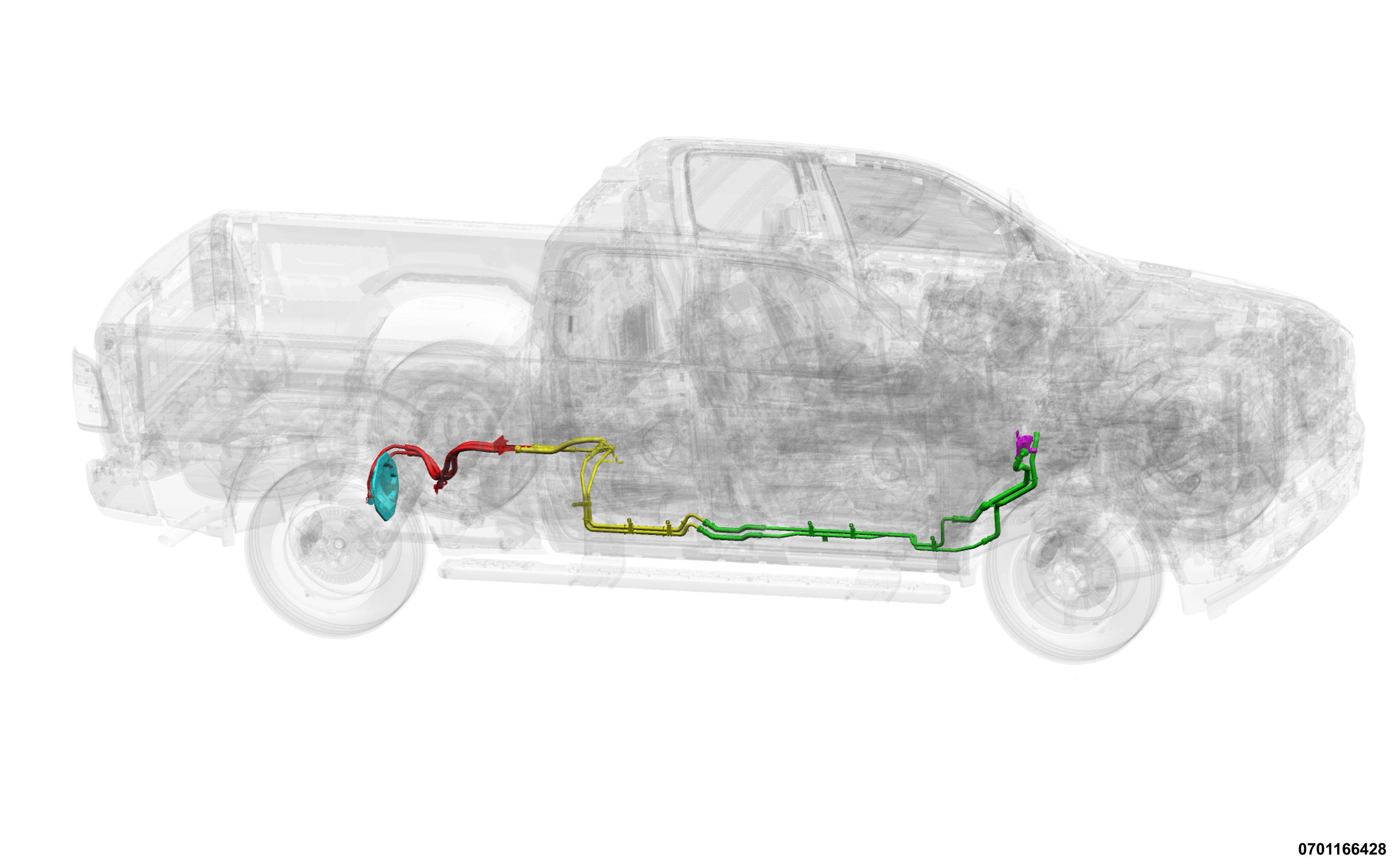 |
Thermal Rear Axle
The Rear Axle Thermal Valve Module (RATVM) is focused on optimizing powertrain heat distribution to reduce powertrain oil viscosity and improve fuel economy. The RATVM moderates coolant flow between the heater core and the rear axle coverer as applicable. The rear axle cover serves as a heat exchanger between the coolant and the rear axle fluid. The Powertrain Control Module (PCM) continuously monitors coolant temperature after the differential heat exchanger and heater core flow demand as requested by the Heating Ventilation Air Conditioning (HVAC) controller. The axle coolant temperature sensor is located on the return side of the axle coolant loop, and provides input to the PCM. The RATVM is positioned such that flow to the axle heater is maximized while still meeting the HVAC demand. Flow to the axle heater can be shut off in order to meet heater core demand and improve engine warm up.