Disassembly and Assembly
C235 - Limited Slip Differential
▸Contents: 03 - Differential and Driveline
Description and Operation
Diagnosis and Testing
ASSEMBLY, Differential
Disassembly and Assembly
Actuator/Motor
GEAR, Ring and Pinion
Removal and Installation
Joints
SHAFTS, Axle/Drive/Half
Valves
Removal and Installation
INSPECTION - Perform the following inspection of the case assembly before disassembling and performing any repairs.
- Bottom out both side gears flat in the case pockets.
- Measure between the differential side gears.
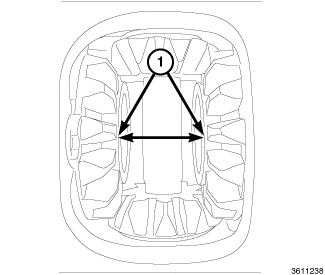
1 – Distance Between Side Gears - If the measurement is greater than 42.25 mm (1.66 in.), the Limited Slip Differential Case assembly must be replaced.
DISASSEMBLY
- Remove the differential carrier from the housing (Refer to 03 - Differential and Driveline/ASSEMBLY, Differential/Removal and Installation) .
- Remove the ring gear from the case and DISCARD the bolts.
1 – Ring Gear 2 – Ring Gear Bolts 3 – Differential Case - Clamp the Fixture, Holding 6963B in a vise and set the differential case on the fixture.
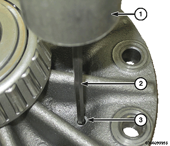
- Remove the differential pinion mate shaft roll pin from differential case using a suitable punch.
1 – Hammer 2 – Pin Punch 3 – Pinion Mate Shaft Roll Pin - Rotate the differential case on the fixture and remove the differential pinion mate shaft.
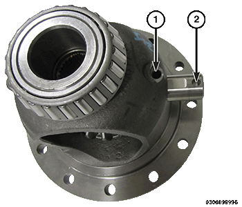
1 – Pinion Mate Shaft Roll Pin Hole 2 – Pinion Mate Shaft - Lubricate and install the disc without the threaded hole from the Trac-Lok Axle Tool C-4487 into lower differential side gear.
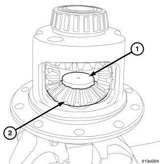
1 – Disc Without Threads 2 – Differential Side Gear - Lubricate and install the upper disc with threaded hole from the Trac-Lok Axle Tool C-4487 into upper differential side gear. Thread forcing screw from the Trac-Lok Axle Tool C-4487 into upper disc until it contacts the lower disc.
NOTE: The slot in the threaded upper disc can be used to prevent it from turning using a screwdriver.
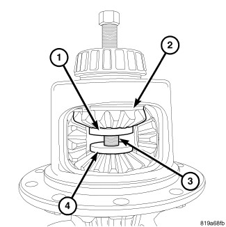
1 – Disc With Threaded Hole 2 – Differential Side Gear 3 – Forcing Screw 4 – Disc Without Threaded Hole - Tighten the forcing screw to compress the belleville springs in the clutch packs. Insert the turning bar from the Trac-Lok Axle Tool C-4487 into the differential pinion mate shaft hole in the differential case.
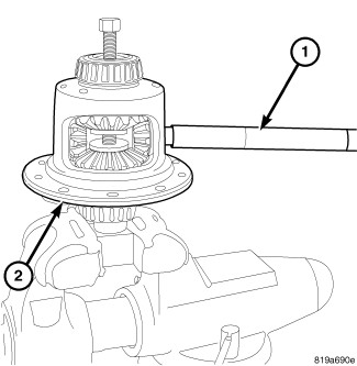
1 – Turning Bar 2 – Differential Case - Rotate the differential case with the turning bar until the differential pinion gears and washers can be removed.
NOTE: Loosen the forcing screw in small increments to relieve the clutch pack tension if the differential case can not be rotated.
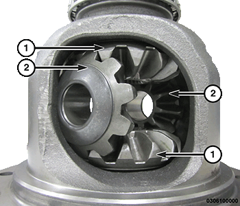
1 – Differential Side Gears 2 – Differential Pinion Gears - Remove the forcing screw, step plate and threaded adapter. Remove the upper clutch pack, clutch pack retainers and the upper differential side gear from the case.
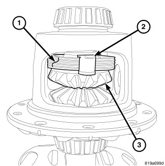
1 – Differential Clutch Pack 2 – Differential Clutch Pack Retainers 3 – Differential Side Gear - Remove the lower clutch pack, clutch pack retainers and lower differential side gear from the case.
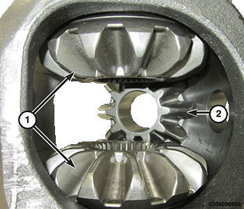
1 – Differential Side Gears 2 – Differential Pinion Gears - Remove the clutch pack retainers, clutch pack belleville spring and the differential side gear. Keep the plates in order during removal.
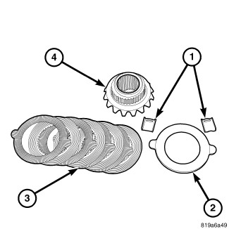
1 – Differential Clutch Pack Retainers 2 – Belleville Spring 3 – Differential Clutch Pack 4 – Differential Side Gear
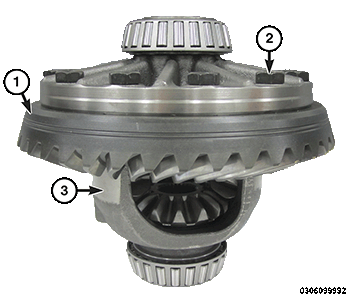
ASSEMBLY
| NOTE: |
New Plates and discs with fiber coating (no grooves or lines) must be presoaked in Friction Modifier before assembly. Soak plates and discs for a minimum of 20 minutes. |
- Lubricate the components with gear lubricant.
- Assemble the differential clutch discs, clutch plates and belleville spring into the packs and secure the disc packs with the retainers.
NOTE: The belleville spring is positioned with the convex side against the differential case.
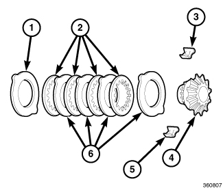
1 – Belleville Spring 2 – Differential Clutch Discs 3 – Differential Clutch Pack Retainer 4 – Differential Side Gear 5 – Differential Clutch Pack Retainer 6 – Differential Clutch Plates - Position the assembled clutch disc packs on the differential side gear hubs.
- Install the lower clutch pack and differential side gear in the differential case, with the retaining clips seated in the case pocket.
1 – Differential Side Gears 2 – Differential Pinion Gears - Install the upper clutch disc pack retaining clips and the differential side gear in the case pocket.
1 – Differential Clutch Pack 2 – Differential Clutch Pack Retainers 3 – Differential Side Gear - Lubricate and install the discs into the differential side gears from the Trac-Lok Axle Tool C-4487 . Install forcing screw from the Trac-Lok Axle Tool C-4487 and the threaded screw to compress the belleville springs in the clutch packs.
1 – Disc With Threaded Hole 2 – Differential Side Gear 3 – Forcing Screw 4 – Disc Without Threaded Hole - Install the side gears in the pinion gears opposite of each other.
- Rotate the differential case with the turning bar from the Trac-Lok Axle Tool C-4487 until the differential pinion gears align with the mate shaft holes in the case.
NOTE: Loosen the forcing screw in small increments to relieve the clutch pack tension if the differential case can not be rotated.
1 – Turning Bar 2 – Differential Case - Install the differential pinion gear thrust washers between the gear and the differential case. Align the washers with the mate shaft hole in the case.
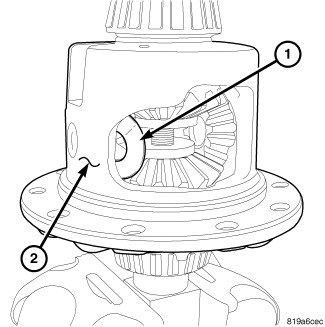
1 – Differential Pinion Gear Thrust Washers 2 – Differential Case - Remove the forcing screw upper disc from the differential side gear.
1 – Differential Side Gears 2 – Differential Pinion Gears - Remove the lower disc from the differential side gear.
- Install the differential pinion mate shaft in the case.
1 – Pinion Mate Shaft Roll Pin Hole 2 – Pinion Mate Shaft - Install the differential pinion mate shaft roll pin Flush to the differential case.
1 – Differential Pinion Mate Shaft Roll Pin 2 – Differential Case - Install the ring gear with NEW ring gear bolts to the case assembly and tighten to the proper (Refer to 03 - Differential and Driveline/Technical Specifications) .
1 – Ring Gear 2 – Ring Gear Bolts 3 – Differential Case - Lubricate all the differential components with gear lubricant.
- Install the differential case into the housing (Refer to 03 - Differential and Driveline/ASSEMBLY, Differential/Removal and Installation) .