Removal and Installation
Pinion Seal - 215fd
▸Contents: 03 - Differential and Driveline
Description and Operation
Diagnosis and Testing
ASSEMBLY, Differential
Disassembly and Assembly
Actuator/Motor
GEAR, Ring and Pinion
Removal and Installation
Joints
SHAFTS, Axle/Drive/Half
Valves
Removal and Installation
- Raise and support the vehicle (Refer to 04 - Vehicle Quick Reference/Hoisting/Standard Procedure) .
- Remove both halfshafts from the axle (Refer to 03 - Differential and Driveline/Halfshaft/Removal and Installation) .
NOTE: It is not necessary to remove the halfshaft from the hub assembly. - Remove the front driveshaft (Refer to 03 - Differential and Driveline/Propeller Shaft/SHAFT, Drive/Removal and Installation) .
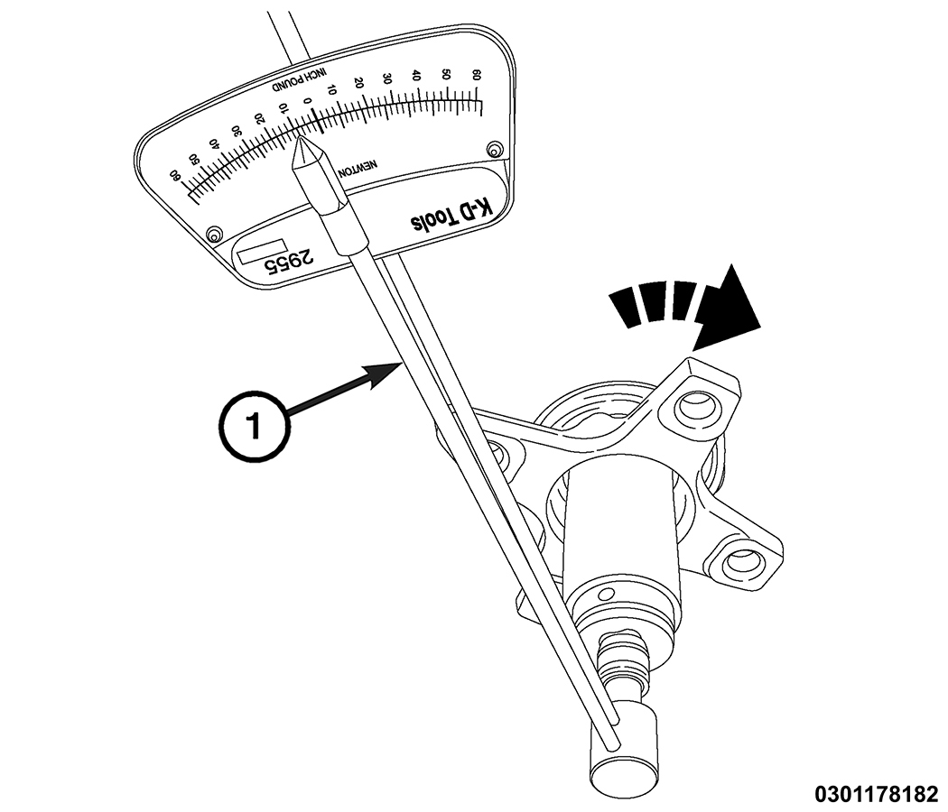
NOTE: The torque reading must be taken with a constant rotational speed. Do not measure break away torque.
- Using a torque wrench, measure and record the pinion rotational torque.
NOTE: Due to axle imbalance concerns and bearing preload sensitivity, it is necessary to verify the pinion nut-to-shaft orientation is maintained. If alignment marks are not visible, apply the appropriate marks before removing the pinion nut.
1 - Torque Wrench - Apply an alignment mark on the pinion flange nut to the pinion shaft and the pinion flange.
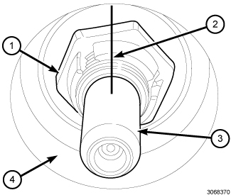
1 - Pinion Flange Nut 2 - Alignment Mark 3 - Pinion Shaft 4 - Pinion Flange - Using Holder, Flange C-3281 and the appropriate socket, remove the pinion flange nut.
NOTE: Due to axle imbalance concerns and bearing preload sensitivity, it is necessary to verify the pinion flange-to-shaft orientation is maintained. If alignment marks are not visible, apply the appropriate marks before removing the pinion flange.
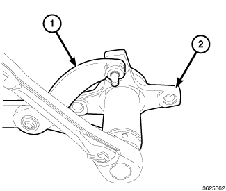
1 - Holder, Flange C-3281 2 - Pinion Flange - Using Puller 1026 , remove the pinion flange from the pinion shaft.
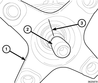
1 - Pinion Flange 2 - Pinion Shaft 3 - Alignment Mark - Using Remover, Seal 7794-A and Slide Hammer, Universal C-637 , remove and DISCARD the pinion seal.
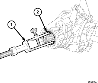
1 - Remover, Seal 7794-A 2 - Pinion Seal
INSTALLATION
Follow the removal procedure in reverse for general reassembly of the components on the vehicle. The steps listed below are calling out specific procedures that should be followed during installation.
- Apply a light coating of gear lubricant to the outer diameter of the flange on the sealing surface.
- Use the Installer, Seal 10398 and Driver Handle, Universal C-4171 to install the NEW pinion seal in the carrier.
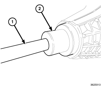
1 - Installer, Seal 10398 2 - Driver Handle, Universal C-4171 - Install the pinion flange into position. Align the index marks between the pinion flange and the pinion stem to maintain assembly balance so bearing preload is not exceeded.
1 - Pinion Flange 2 - Pinion Shaft 3 - Alignment Mark - Using Installer, Bearing/Gear 6448A , lightly tap on the pinion flange until adequate pinion shaft threads are exposed.
- Clean any thread locker from the pinion flange nut and the pinion shaft and apply Mopar® Lock and Seal Adhesive to the nut.
1 - Holder, Flange C-3281 2 - Pinion Flange - Install the pinion flange nut. Apply axle grease to the pinion nut washer face prior to assembly. Use the Holder, Flange C-3281 and the appropriate socket to tighten the pinion flange nut in small increments until the pinion nut index mark aligns with the index marking on the pinion stem.
NOTE: If the pinion nut index mark exceeds the pinion stem index mark the unit must be discarded. If the pinion nut index mark falls short of the pinion stem index mark the unit will possibly generate a Noise, Vibration, or Harshness (NVH) concern.
NOTE: The torque reading must be taken with a constant rotational speed. Do not measure break away torque.
1 - Torque Wrench - Using a torque wrench, measure and record the pinion rotational torque.
1 - Pinion Flange Nut 2 - Alignment Mark 3 - Pinion Shaft 4 - Pinion Flange - After the torque reading has been obtained, compare the reading to the recorded reading when removing the pinion flange. The difference in the reading should be within 0 ± 0.2 N.m (0 ± 1.7 in. lbs.). The value after the repair should be higher due to tighter fit of a new seal.
 TORQUE SPECIFICATIONS - 215FD FRONT AXLE