Removal and Installation
Front Driveshaft
▸Contents: 03 - Differential and Driveline
Description and Operation
Diagnosis and Testing
ASSEMBLY, Differential
Disassembly and Assembly
Actuator/Motor
GEAR, Ring and Pinion
Removal and Installation
Joints
SHAFTS, Axle/Drive/Half
Valves
Removal and Installation
REMOVAL
- Raise and support the vehicle (Refer to 04 - Vehicle Quick Reference/Hoisting/Standard Procedure) .
- If equipped, remove the skid plate (Refer to 13 - Frame and Bumpers/Under Body Protection/PLATE, Skid/Removal and Installation) .
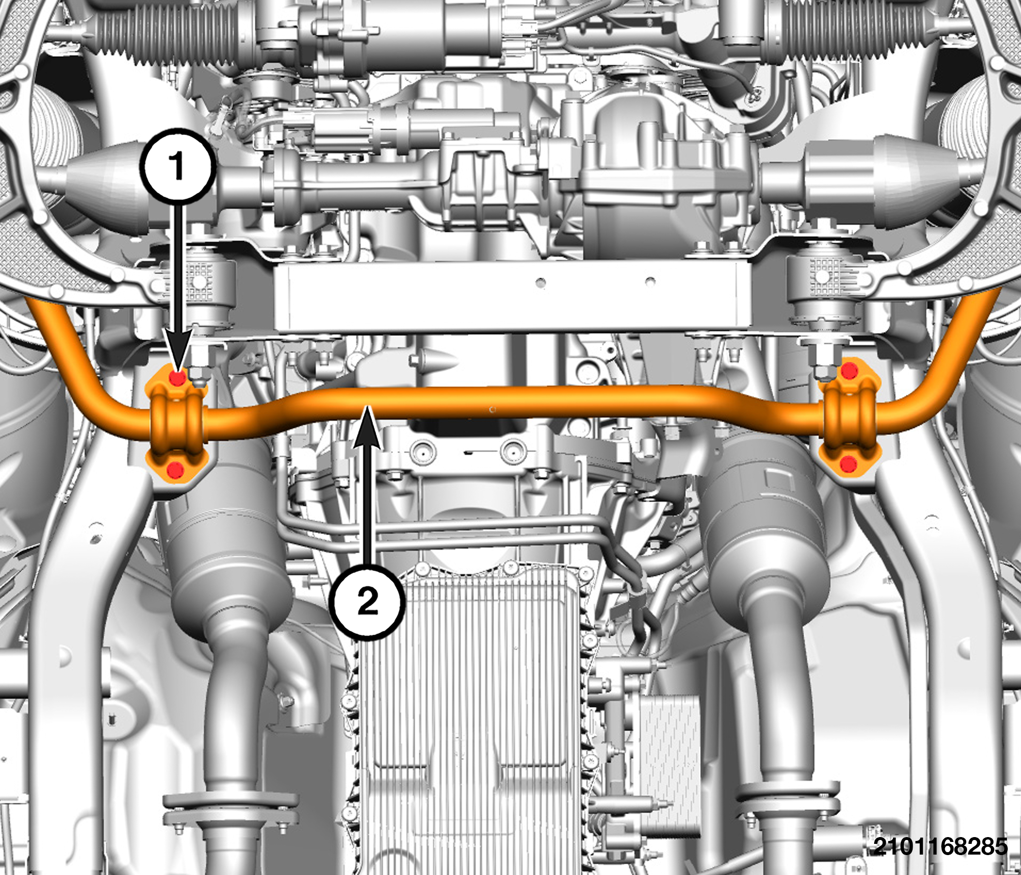
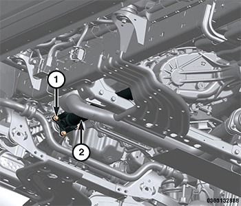
- Remove the stabilizer bar bushing bolts and let the stabilizer bar hang.
1 - Stabilizer Bar Bushing Bolts 2 - Stabilizer Bar - Mark a line across the axle companion flange, driveshaft, flange yoke and transfer case for installation reference.
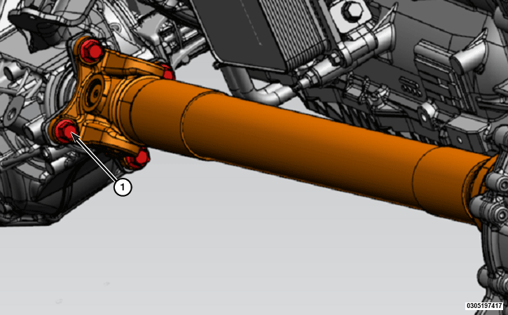
- Remove and DISCARD the front driveshaft to front axle bolts.
1 - Driveshaft To Front Axle Bolts 2 - Front Driveshaft - Remove the front driveshaft.
INSPECTION:
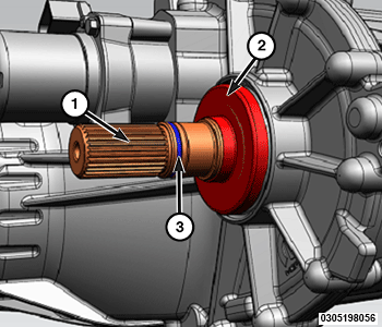
- Clean and inspect the front output shaft splines.
- Inspect the front output shaft O-ring, replace if damaged.
1 - Front Output Shaft Splines 2 - Front Output Shaft Oil Seal Slinger 3 - Front Output Shaft O-Ring
INSTALLATION
Follow the removal procedure in reverse for general reassembly of the components on the vehicle. The steps listed below are calling out specific procedures that should be followed during installation.
- Install the front driveshaft with all the reference marks aligned.
- Install NEW front driveshaft to front axle bolts.
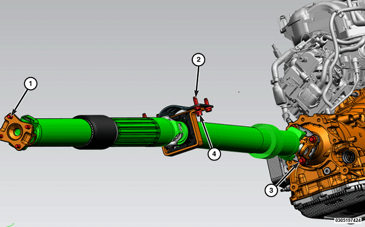
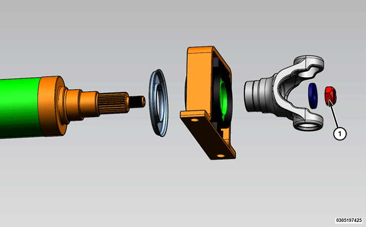
 TORQUE SPECIFICATIONS - DRIVESHAFT