Removal and Installation
Pinion Seal - Rba260
▸Contents: 03 - Differential and Driveline
Description and Operation
Diagnosis and Testing
ASSEMBLY, Differential
Disassembly and Assembly
Actuator/Motor
GEAR, Ring and Pinion
Removal and Installation
Joints
SHAFTS, Axle/Drive/Half
Valves
Removal and Installation
REMOVAL
- Raise and support the vehicle (Refer to 04 - Vehicle Quick Reference/Hoisting/Standard Procedure) .
- Remove the driveshaft (Refer to 03 - Differential and Driveline/SHAFTS, Axle/Drive/Half/Removal and Installation) .
- Remove the brake rotors to prevent drag (Refer to 05 - Brakes, Base/Hydraulic/Mechanical/ROTOR, Brake/Removal and Installation) .
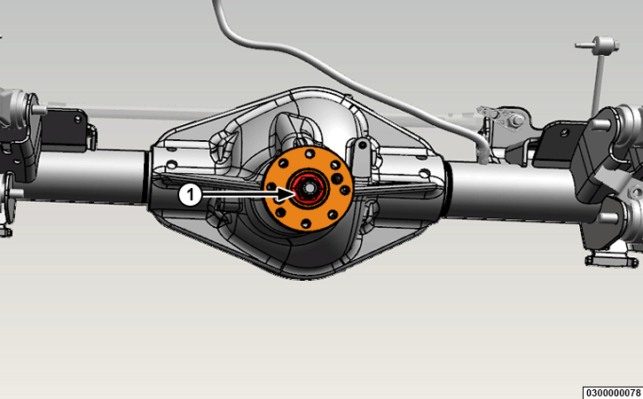
- Rotate the companion flange three or four times.
- Rotate the companion flange and record the Pinion Torque To Rotate (PTTR) resistance using an inch pound torque wrench.
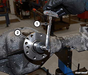
1 – Inch Pound Torque Wrench 2 – Companion Flange - Install the bolts into two of the threaded holes in the companion flange 180° apart.
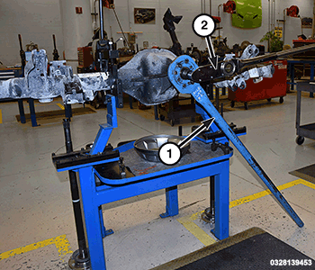
1 – Torque Wrench 2 – Holder, Yoke - Position Holder, Yoke 6719A against the companion flange and install a bolt and washer into one of the remaining threaded holes. Tighten the bolts so the yoke holder is held to the flange.
- Remove the companion flange nut.
- Mark a line across the pinion shaft and flange for installation reference.
- Remove the companion flange using Puller, Companion Flange C-452 .
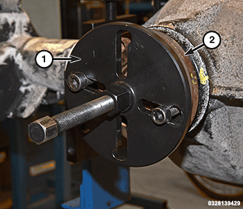
1 – Puller, Companion Flange C-452 2 – Companion Flange - Remove the pinion seal using a seal puller or suitable tool.
INSTALLATION
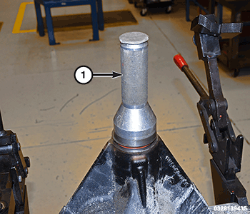 |
|
|
| 1 – Installer, Seal 2089000030 |
- Install a NEW pinion seal using Installer, Seal 2089000030.
- Install the flange on the pinion shaft with the reference marks aligned.
- Install two bolts into the threaded holes in the companion flange, 180° apart.
- Position Holder, Yoke 6719A against the companion flange and install a bolt and washer into one of the remaining threaded holes. Tighten the bolts so the tool is held to the flange.
- Align the marks on the pinion shaft and the companion flange and install the companion flange on the pinion shaft using Installer, 22088600030 and Holder, Yoke 6719A .
- Install a NEW pinion nut.
1 – Pinion Nut Staking Locations 2 – Pinion Nut - Hold the companion flange using Holder, Yoke 6719A and tighten the NEW pinion nut using a torque wrench to the proper torque specification.
- Rotate the pinion several times to ensure the pinion bearings are seated.
1 – Inch Pound Torque Wrench 2 – Companion Flange - Measure the PTTR with an inch pound torque wrench. PTTR should be equal to recorded reading plus an additional 0.56 N⋅m (5 In. Lbs.). If PTTR is low, tighten the pinion nut in 6.8 N⋅m (5 Ft. Lbs.) increments until the PTTR is achieved.
CAUTION: Never loosen pinion nut to decrease pinion bearing rotating torque. If pinion torque to rotating is exceeded, a new collapsible spacer must be installed. Failure to follow these instructions will result in damage to the axle.
NOTE: Once the proper PTTR is achieved, the pinion nut must be staked to the pinion to prevent pinion nut movement. - Align the reference marks and install the driveshaft (Refer to 03 - Differential and Driveline/SHAFTS, Axle/Drive/Half/Removal and Installation) .
- Install the rear brake components (Refer to 05 - Brakes, Base/Hydraulic/Mechanical/ROTOR, Brake/Removal and Installation) .
- Remove the support and lower the vehicle.
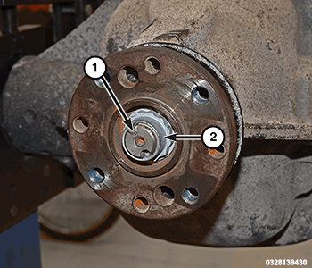
 TORQUE SPECIFICATIONS - RBA260 INTERNAL