Removal and Installation
Ring And Pinion Gear - M250
▸Contents: 03 - Differential and Driveline
Description and Operation
Diagnosis and Testing
ASSEMBLY, Differential
Disassembly and Assembly
Actuator/Motor
GEAR, Ring and Pinion
Removal and Installation
Joints
SHAFTS, Axle/Drive/Half
Valves
Removal and Installation
REMOVAL
| NOTE: |
The ring and pinion gears are serviced as a matched set. Never replace one without replacing the other. |
- Remove the differential case assembly from the axle housing (Refer to 03 - Differential and Driveline/ASSEMBLY, Differential/Removal and Installation) .
- Remove the Axle Locker Actuator (Refer to 03 - Differential and Driveline/ACTUATOR/MOTOR/Removal and Installation) .
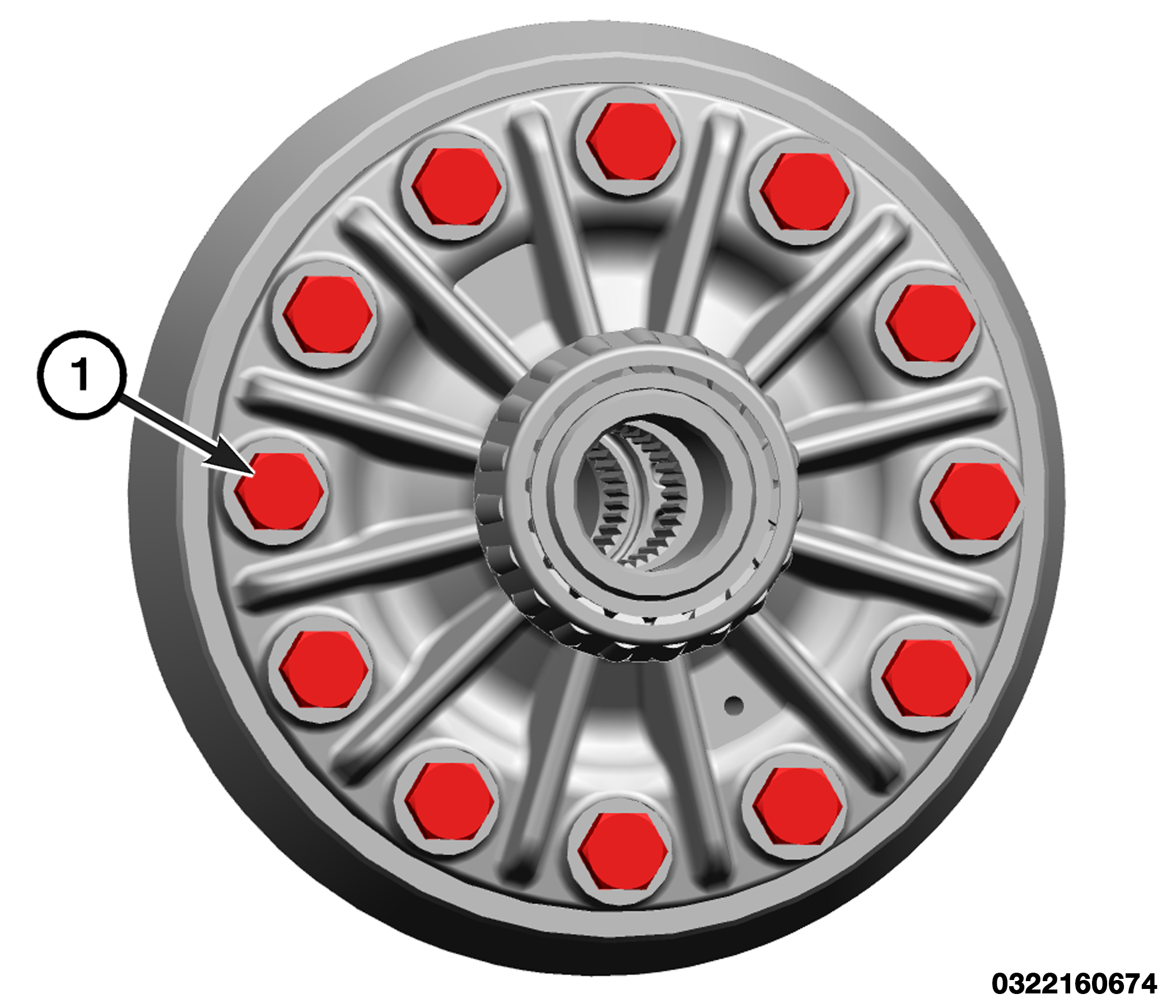
- Remove and DISCARD the ring gear bolts and remove the ring gear from the differential case assembly.
1 – Ring Gear Bolts - Remove the pinion drive seal (Refer to 03 - Differential and Driveline/ACTUATOR/MOTOR/Removal and Installation) .
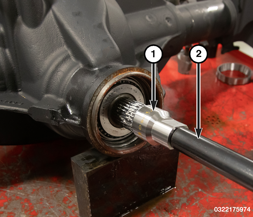
- Remove the pinion gear from the housing using Pinion Driver 2076300030 , Driver Handle, Universal C-4171 , and dead blow hammer.
1 – Pinion Driver 2076300030 2 – Driver Handle, Universal C-4171 - Remove and DISCARD the collapsible spacer from the pinion gear shaft.
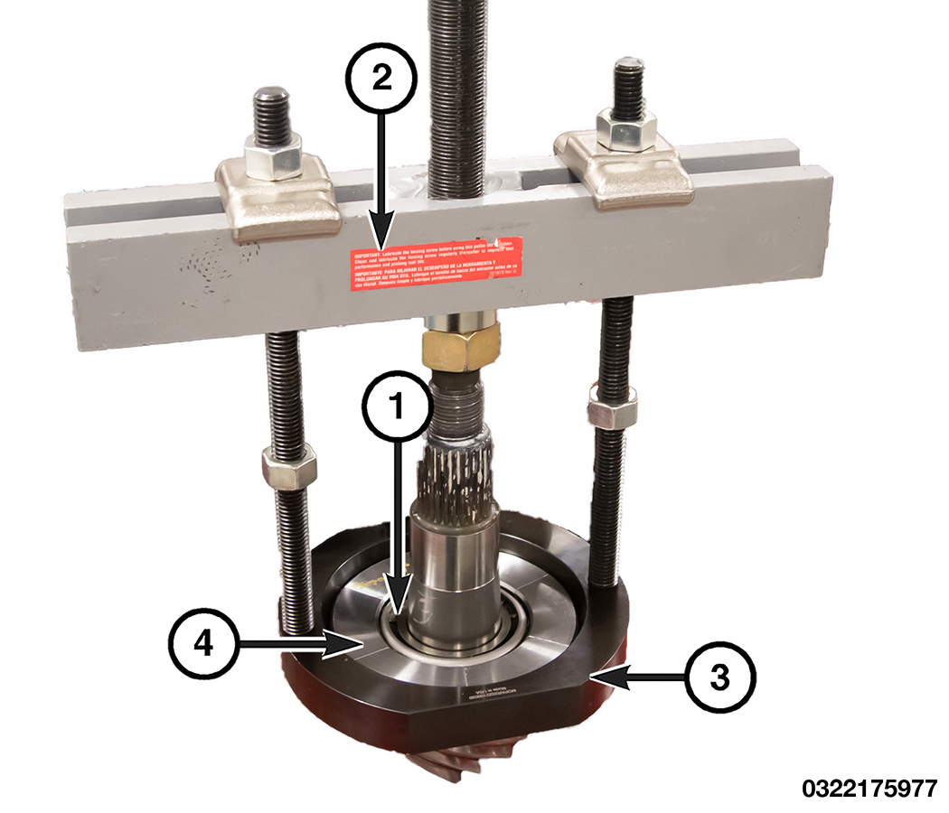
- Remove the rear pinion bearing from pinion gear shaft using the Bridge 938 , Puller Press, Carrier Bearing 2022100030 , and Pinion Head Bearing Remover Blocks 2076400030 .
1 – Rear Pinion Bearing 2 – Bridge 938 3 – Puller Press, Carrier Bearing 2022100030 4 – Pinion Head Bearing Remover Blocks 2022102030 - Remove the selectable washer from behind the rear pinion bearing head.
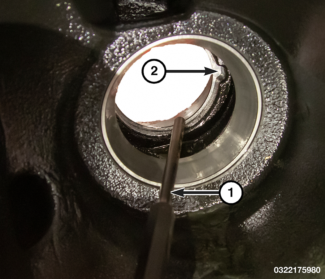
- Remove the front pinion bearing cup from the axle housing using a brass drift punch.
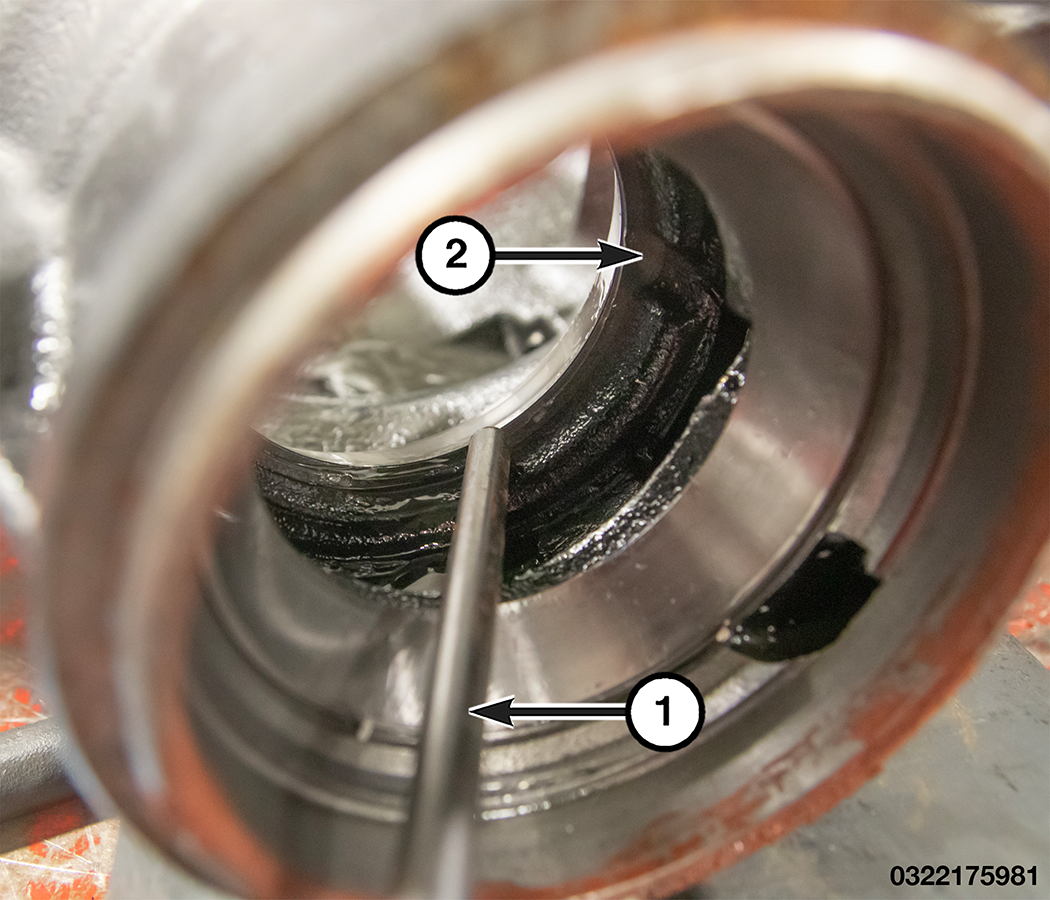
1 – Brass Drift Punch 2 – Front Pinion Bearing Cup - Remove the rear pinion bearing cup from the axle housing using a brass drift punch.
1 – Rear Pinion Bearing Cup 2 – Brass Drift Punch
INSTALLATION
| NOTE: |
If replacing the ring and pinion gears perform the pinion height, differential bearing preload, the backlash and gear contact adjustment procedures (Refer to 03 - Differential and Driveline/Adjustments) . |
- Install the selectable washer into the case before installing the rear bearing cup.
- Install the NEW rear bearing cup using the Pinion Head Brg Race Installer 2076100030 and Driver Handle, Universal C-4171 .
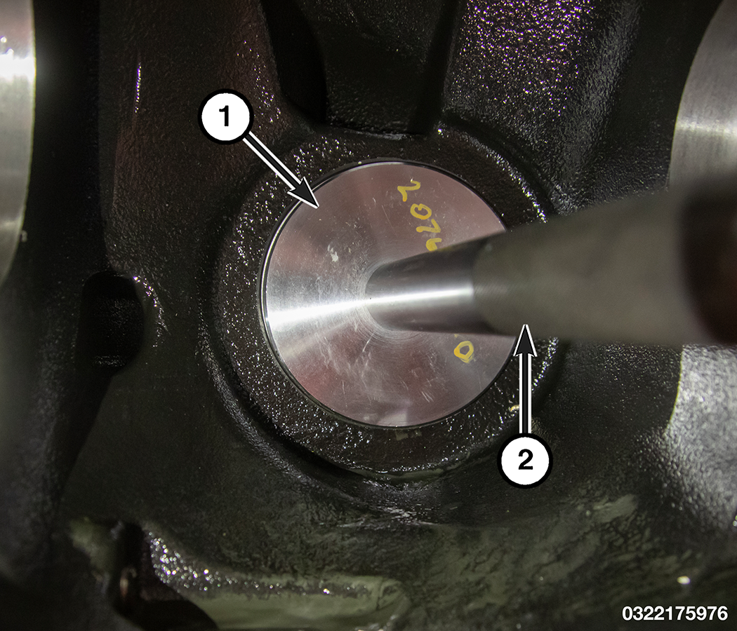
1 – Pinion Head Bearing Race Installer 2076100030 2 – Driver Handle, Universal C-4171 - Install the NEW front bearing cup using the Installer, Bearing C-4310 and Driver Handle, Universal C-4171 .
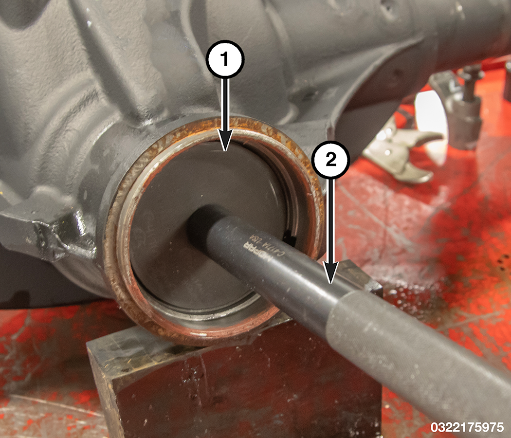
1 – Installer, Bearing C-4310 2 – Driver Handle, Universal C-4171 - Install the NEW front pinion bearing.
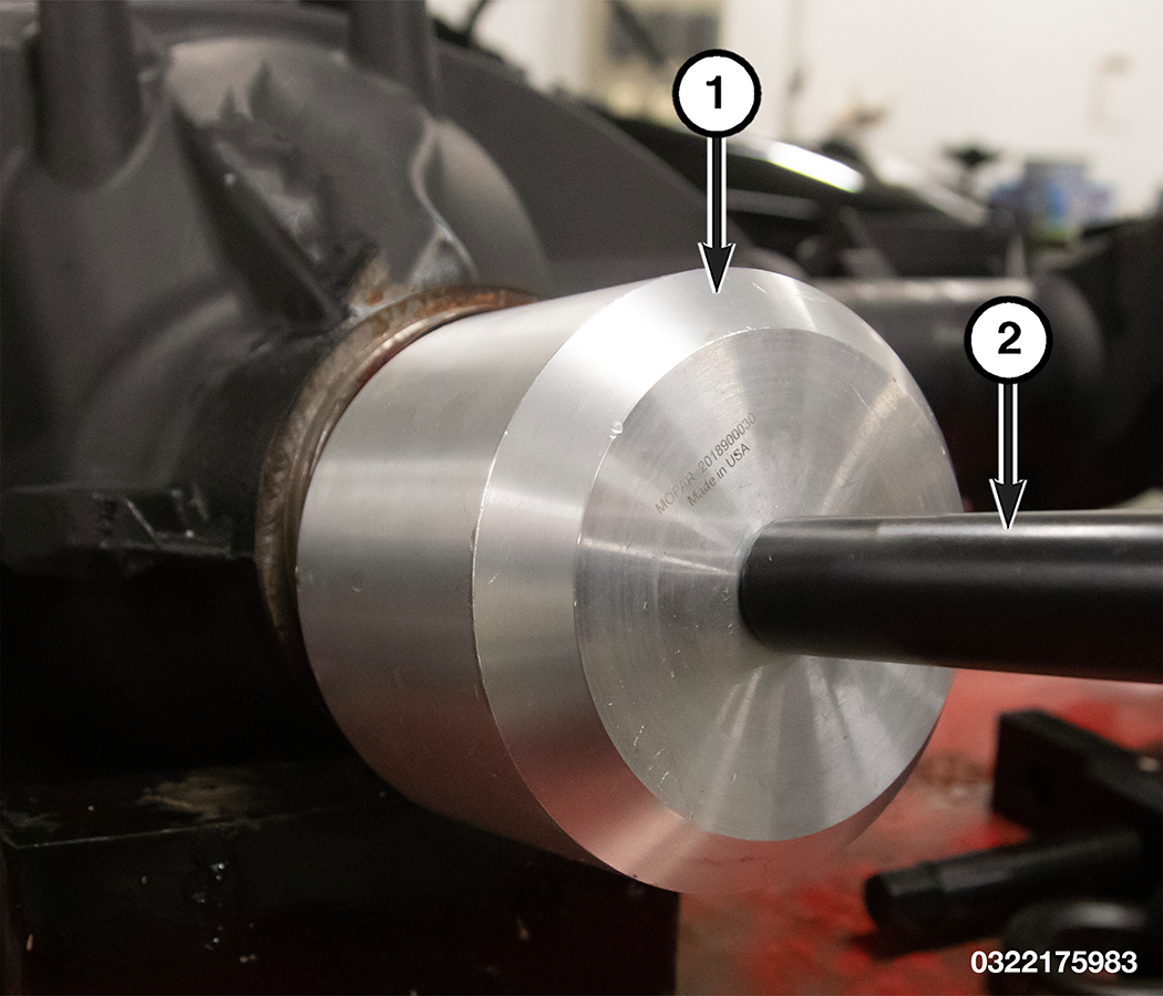
- Apply a light coating of gear lubricant on the lip of the NEW pinion seal. Install the pinion seal using the Installer, Pinion Seal 2018900030 and Driver Handle, Universal C-4171 .
1 – Installer, Pinion Seal 2018900030 2 – Driver Handle, Universal C-4171 - Install the selectable washer to the rear pinion bearing head.
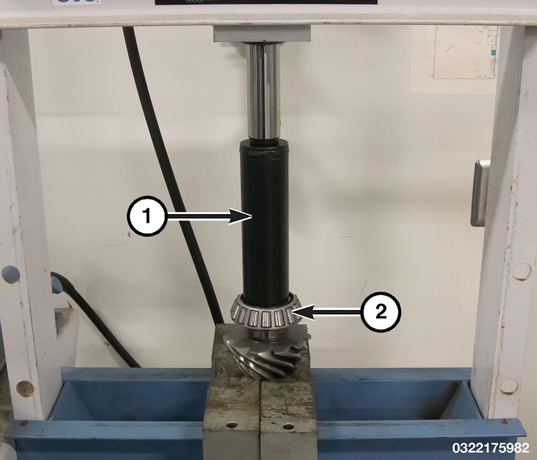
- Install the NEW rear pinion bearing on the pinion gear using the Installer, Bearing C-3095-A and a press.
1 – Installer, Bearing C-3095-A 2 – Rear Pinion Bearing - Install a NEW collapsible spacer on the pinion shaft.
- Install the pinion gear into the axle housing.
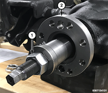
1 – Pinion Flange Installer 2076200030 2 – Pinion Flange - Install the pinion flange using the Pinion Flange Installer 2076200030 .
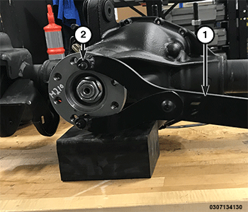
- Install a NEW pinion nut. Hold the pinion flange with Wrench, Spanner 6958 and tighten the pinion nut.
1 – Wrench, Spanner 6958 2 – Bolts - Tighten the pinion nut in 6.8 N·m (5 ft. lbs.) increments until the Pinion Torque To Rotate (PTTR) specification is achieved.
- Measure PTTR after each 6.8 N·m (5 ft. lbs.) increment with an inch pound torque wrench. Refer to (Refer to 03 - Differential and Driveline/Technical Specifications) for PTTR specifications. Record measurement.
1 – Inch Pound Torque Wrench - Install the ring gear to the differential and fasten with NEW ring gear bolts.
1 – Ring Gear Bolts - Install the Axle Locker Actuator (Refer to 03 - Differential and Driveline/ACTUATOR/MOTOR/Removal and Installation) .
- Install the differential case assembly (Refer to 03 - Differential and Driveline/ASSEMBLY, Differential/Removal and Installation) .
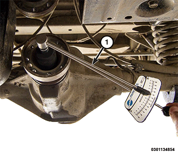
- Measure the Total Torque To Rotate (TTTR) with an inch pound torque wrench before installing the axle shafts. Refer to (Refer to 03 - Differential and Driveline/Technical Specifications) for TTTR specifications.
1 – Inch Pound Torque Wrench
| NOTE: |
If TTTR is too high, decrease the washer thickness equally from both sides of the differential and check TTTR again. If TTTR is too low, increase the washer thickness equally to both sides of the differential and check TTTR again. |
 TORQUE SPECIFICATIONS - M250 DIFFERENTIAL