Adjustments
Adjustments - Rba260
▸Contents: 03 - Differential and Driveline
Description and Operation
Diagnosis and Testing
ASSEMBLY, Differential
Disassembly and Assembly
Actuator/Motor
GEAR, Ring and Pinion
Removal and Installation
Joints
SHAFTS, Axle/Drive/Half
Valves
Removal and Installation
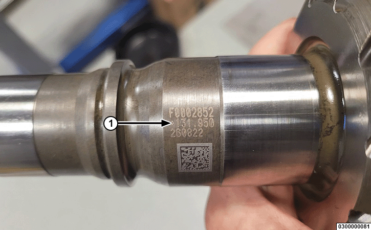 |
The ring gear and pinion gears are supplied as matched sets. The numbers for the ring and pinion gears are laser etched onto the pinion gear shaft and the side of the ring gear. The first number is the gear set sequence number and will be the same for the pinion and ring gear. The second line has a plus (+) followed by a variance number. The third line is the last six digits of the part number.
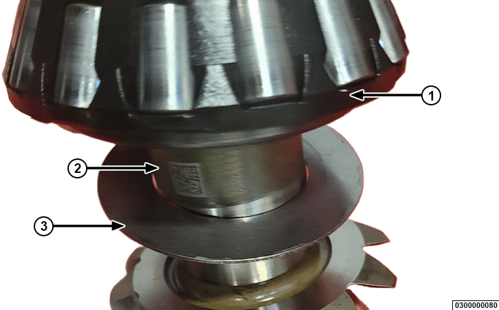
Compensation for pinion gear depth variance is achieved with select shims. The shim is placed on the pinion gear behind the rear pinion bearing.
Calculating the pinion depth variance will require some simple math. Subtract the number etched in the pinion from the standard pinion depth of 132.00 in millimeters.
Example 1: New pinion has a marking of 132.015. Subtract 132.015 from 132.00. (132.000 - 132.015 = negative (-) 0.015 mm).
Example 2: New pinion has a marking of 131.955. Subtract 131.955 from 132.00 (132.00 - 131.955 = positive (+) 0.045 mm).
This will indicate a positive (+) or negative (-) number and will be added or subtracted from the calculated shim thickness later in the procedure. Record the calculated pinion depth variance, positive (+) or negative (-), for later use.
PINION DEPTH MEASUREMENT
 |
|
|
|
|
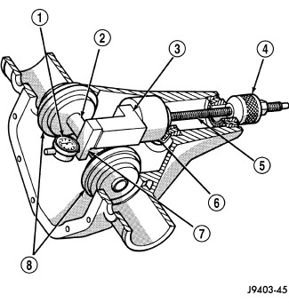
| 1 – Dial Indicator | 2 – Arbor |
| 3 – Height Block | 4 – Cone |
| 5 – Screw | 6 – Pinion Height Gauge |
| 7 – Scooter Block | 8 – Arbor Discs |
Measurements are taken with the pinion bearing cups and pinion bearings installed in the housing. Take the measurements with Set, Dial Indicator C-3339A .
- Assemble Block, Height 6739 , Gauge, Height Block RB260 55.80mm 2088200030 and the rear pinion bearing onto Screw 6741 .
- Insert the pinion block, pinion height block, rear bearing, and screw into the housing through the pinion bearing cups.
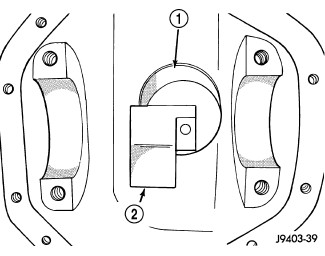
1 – Pinion Height Gauge 2 – Height Block - Install a NEW front pinion bearing and Cone 6740 on the screw. Tighten the cone-nut until the Torque To Rotate (TTR) of the screw is 2.5 N·m (22 in. lbs.).
NOTE: Do not reuse pinion bearings.
- Place Bearing, Dummy RB260 (Qty 2) 2088300030 on Arbor D-115-3 in position in the housing side bearing cradles. Install the differential bearing caps on the arbor discs and tighten the cap bolts to 41 N·m (30 ft. lbs.).
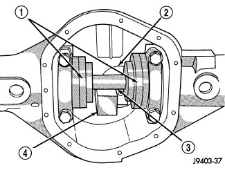
1 – Arbor Discs 2 – Pinion Height Gauge 3 – Arbor 4 – Height Block - Assemble Set, Dial Indicator C-3339A into Block, Scooter D-115-2A and secure the set screw.
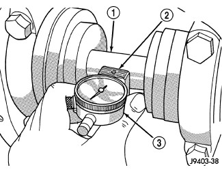
1 – Arbor 2 – Scooter Block 3 – Dial Indicator - Place the Scooter Block/Dial Indicator in position in the axle housing so that the dial probe and scooter block are flush against the rearward surface of the pinion height block. Hold the scooter block in place and zero the dial indicator. Tighten the dial indicator face locking screw.
- Slide the dial indicator probe across the gap between the pinion height block and the arbor bar with the scooter block against the pinion height block. Continue moving the dial probe to the crest of the arbor bar and record the highest reading.
- Select a pinion depth shim equal to the dial indicator reading plus or minus the pinion depth variance calculated earlier. If the calculated pinion depth variance recorded earlier is positive (+), ADD the calculated number from the dial indicator reading. If the calculated pinion depth variance recorded earlier is negative (-), SUBTRACT the calculated number to the dial indicator reading.
NOTE: Shim thickness = Dial indicator reading plus (+) the pinion depth variance.
Example 1: Shim thickness = 1.90 mm (dial indicator reading) plus (+) +0.045 mm (a positive pinion depth variance) = 1.945 mm.
Example 2: Shim thickness = 1.90 mm (dial indicator reading) plus (+) - 0.015 mm (a negative pinion depth variance) = 1.885 mm.
1 - Pinion Bearing 2 - Pinion Shaft 3 - Pinion Depth Shim - Install a NEW bearing with the select pinion depth shim as close as possible to the calculated number behind the rear pinion bearing.
NOTE: The pinion bearings, bearing cups and pinion seal MUST be replaced when making shim adjustment changes . - Install the ring and pinion gear (Refer to 03 - Differential and Driveline/GEAR, Ring and Pinion/Removal and Installation) .
DIFFERENTIAL BEARING PRELOAD AND GEAR BACKLASH
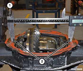
- Before installing the differential, use a 12 inch caliper to measure between the inner most part of the machinerd holes and record reading for later use.
- Install the differential and bearing caps and tighten to 14 N·m (10 ft. lbs.) to retain cups while adjusting.
1 – Caliper 2 – Machined Holes - Turn both thread adjusters inward using Wrench, Differential Preload C-4164 until the differential bearing end-play is eliminated and the ring gear backlash is approximately 0.025 mm (0.001 in.). Seat the bearing cups by rapidly rotating the pinion gear a half turn back and forth several times.
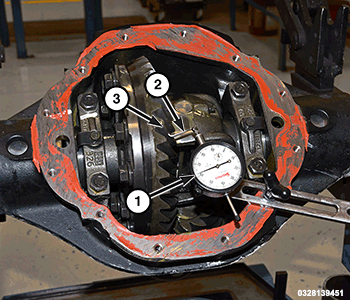
1 – Dial Indicator 2 – Plunger Ring Gear Tooth - Install the dial indicator with the plunger positioned against the drive side of a ring gear tooth. Measure and record the backlash at 4 positions, 90 degrees apart around the ring gear. Mark the lowest backlash position on the ring gear and make all backlash measurements at this location.
- Loosen the left-side adjuster and tighten the right-side threaded adjuster using Wrench, Differential Preload C-4164 to obtain a backlash of 0.076 - 0.102 mm (0.003 - 0.004 in.).
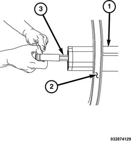
1 – Axle Tube 2 – Backing Plate 3 – Differential Preload Wrench - Tighten both adjusters to 14 N·m (10 ft. lbs.). Seat the differential bearing cups by rapidly rotating the pinion gear a half turn back and forth several times.
- Tighten the differential bearing cap bolts 136 N·m (100 ft. lbs.).
- Tighten the right-side threaded adjuster to 102 N·m (75 ft. lbs.). Seat the differential bearing cups by rapidly rotating the pinion gear a half turn back and forth several times. Continue this procedure until the right-side adjuster torque remains a constant 102 N·m (75 ft. lbs.).
- Measure the ring gear backlash. Backlash should be 0.05 - 0.20 mm (0.002 - 0.008 in.). If the backlash is less than 0.05 mm (0.002 in.) increase the torque on the right-side threaded adjuster until the specified backlash is obtained. If the backlash is more than 0.20 mm (0.008 in.) repeat the procedure from the beginning.
- Tighten the left-side threaded adjuster to 102 N·m (75 ft. lbs.). Seat the differential bearing cups by rapidly rotating the pinion gear a half turn back and forth several times. Continue this procedure until the left-side adjuster torque remains a constant 102 N·m (75 ft. lbs.).
- Use a 12 inch caliper to measure between the inner most part of the machined holes and compare between the reading recorded in earlier step.
1 – Caliper 2 – Machined Holes - Subtract the first reading from the second reading. Case spread should have increased between 0.050 mm (0.002 in) and 0.100 mm (0.004 in). If below 0.050 mm (0.002 in), increase the torque evenly on both threaded adjusters and recheck the backlash. If case spread is above 0.100 mm (0.004 in), decrease the torque evenly on both of the threaded adjusters and recheck the backlash.
- Install the threaded adjuster locks and tighten the lock screws to 11 N·m (97 in. lbs.).
- Measure the backlash at 4 positions, 90 degrees apart around the ring gear. The maximum ring gear backlash variation is 0.076 mm (0.003 in.).
GEAR CONTACT PATTERN
- Wipe each ring gear tooth clean.
- Apply gear marking compound to all of the ring gear teeth.
- Verify the bearing cap bolts are torqued to the proper (Torque Specifications) .
- Apply the parking brake lightly to create approximately 14 N·m (10 ft. lbs.) of pinion rotating torque.
NOTE: If the axle is not in the vehicle, a large screwdriver can be used between the outer smooth edge of the ring gear and the axle housing to provide resistance.
- Rotate the pinion/pinion flange 4 full revolutions in each direction.
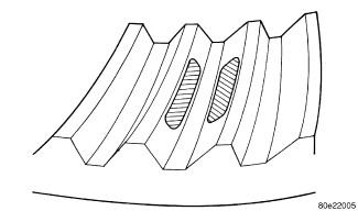
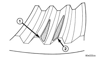
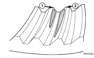
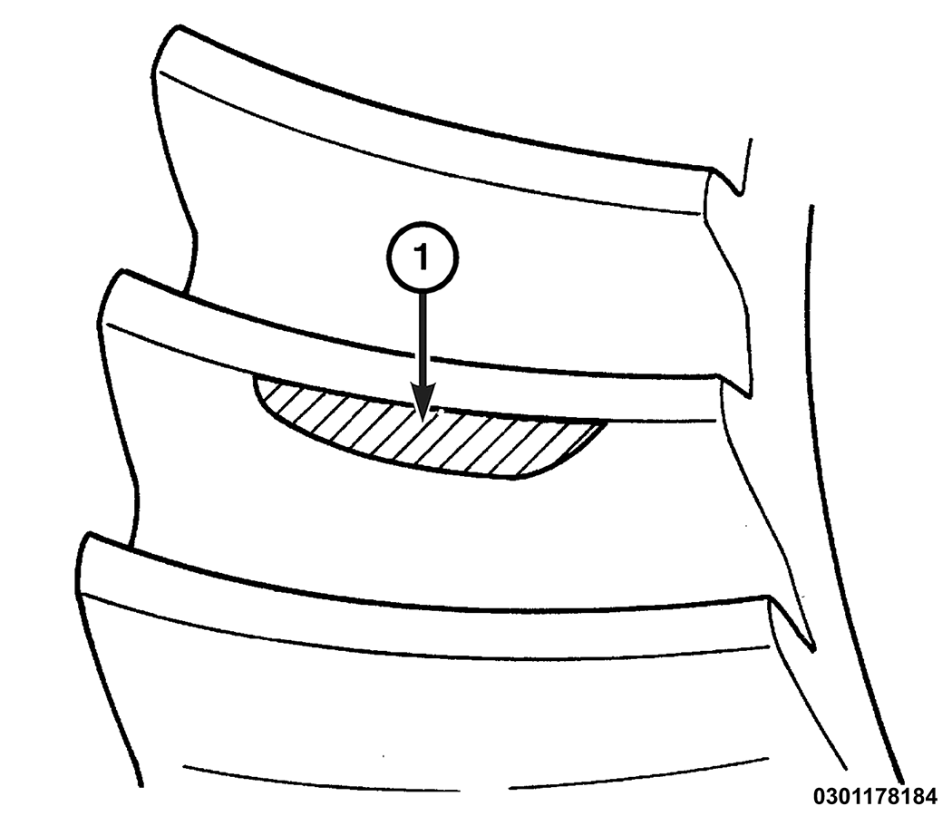
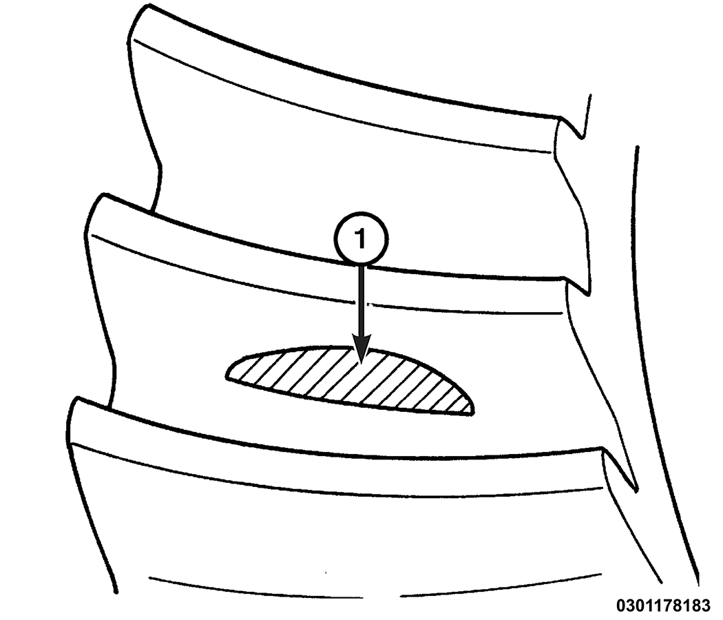
- Read the gear tooth contact pattern and compare it to the following patterns:
 |
|
|
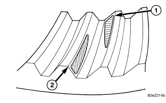
| 1 - Coast Side Toe |
| 2 - Drive Side Heel |
The ring gear is too far away from the pinion gear. Decrease the backlash by moving the ring gear closer to the pinion gear using the adjusters.
 |
|
|
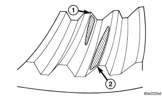
| 1 - Drive Side Toe |
| 2 - Coast Side Heel |
The ring gear is too close to the pinion gear. Increase the backlash by moving the ring gear away from the pinion gear using the adjusters.
 |
|
|
| 1 - Drive Side Heel |
| 2 - Coast Side Heel |
The ring gear is too far away from the pinion gear. Decrease the backlash by moving the ring gear closer to the pinion gear using the adjusters.
 |
|
|
| 1 - Drive Side Toe |
| 2 - Coast Side Toe |
The ring gear is too close to the pinion gear. Increase the backlash by moving the ring gear away from the pinion gear using the adjusters.
 |
|
|
| 1 - Ring Gear |
The pinion gear is set too far from the ring gear. Decrease pinion gear distance by increasing the pinion depth shim thickness.
 |
|
|
| 1 - Ring Gear |
The pinion gear is set too close to the ring gear. Increase pinion distance by decreasing the pinion depth shim thickness.
| NOTE: |
It may be necessary to adjust the backlash after adjusting the pinion distance. |
SIDE GEAR CLEARANCE
Visually inspect the differential case, pinion mate shaft, axle shaft end button, C-lock, differential pinion gears, differential side gears and washers for damage or excessive wear. Replace damaged components.
- Assemble the differential and install.
- Install the differential pinion mate shaft locking screw and hand tighten to locate the shaft.
- Mount the dial indicator base on the axle tube flange.
1 - Dial Indicator Base 2 - Axle Tube Flange 3 - Dial Indicator 4 - Dial Indicator Plunger 5 - Axle Shaft - Push the axle shaft inward until the end touches the differential pinion mate shaft. Set the dial indicator plunger on the end of axle shaft flange surface and zero the dial indicator.
- Pull the axle shaft out until it stops and record the dial indicator end-play reading. Rotate the axle shaft about 180 degrees and record the dial indicator end-play reading again. The two readings should be within 0.05 mm (0.002 in.).
- Conduct the same procedure on the axle shaft on the opposite side.
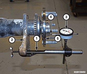
The end-play specification should be 0.13 mm - 0.38 mm (0.005 - 0.015 in.). If the specification can not be met, it may be necessary to re-shim the side gears or replace the differential case.