Removal and Installation
Pinion Seal - M250
▸Contents: 03 - Differential and Driveline
Description and Operation
Diagnosis and Testing
ASSEMBLY, Differential
Disassembly and Assembly
Actuator/Motor
GEAR, Ring and Pinion
Removal and Installation
Joints
SHAFTS, Axle/Drive/Half
Valves
Removal and Installation
REMOVAL
- Raise and support the vehicle (Refer to 04 - Vehicle Quick Reference/Hoisting/Standard Procedure) .
- Remove the rear brake rotors (Refer to 05 - Brakes, Base/Hydraulic/Mechanical/ROTOR, Brake/Removal and Installation) .
- Remove the rear driveshaft (Refer to 03 - Differential and Driveline/SHAFTS, Axle/Drive/Half/Removal and Installation) .
- Rotate the pinion gear three or four times.
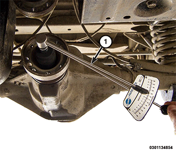
- Record Pinion Torque To Rotate (PTTR) reading with an inch pound torque wrench.
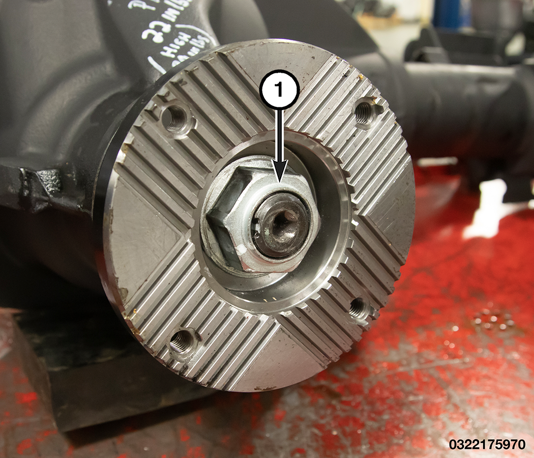
1 - Inch Pound Torque Wrench - Hold the pinion flange with Wrench, Spanner 6958 and remove the pinion nut.
1 - Pinion Nut - Mark a line across the pinion shaft and flange for installation reference.
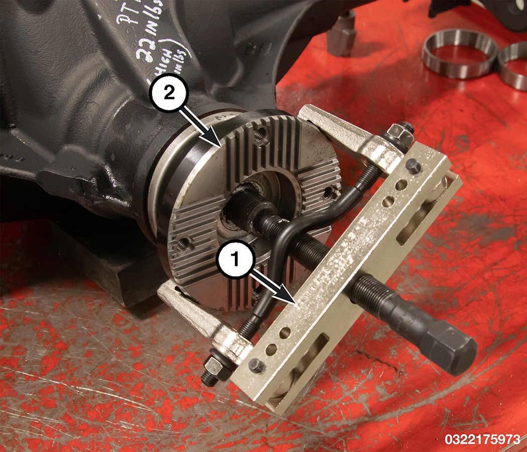
- Remove the pinion flange using a commercially available two jaw puller.
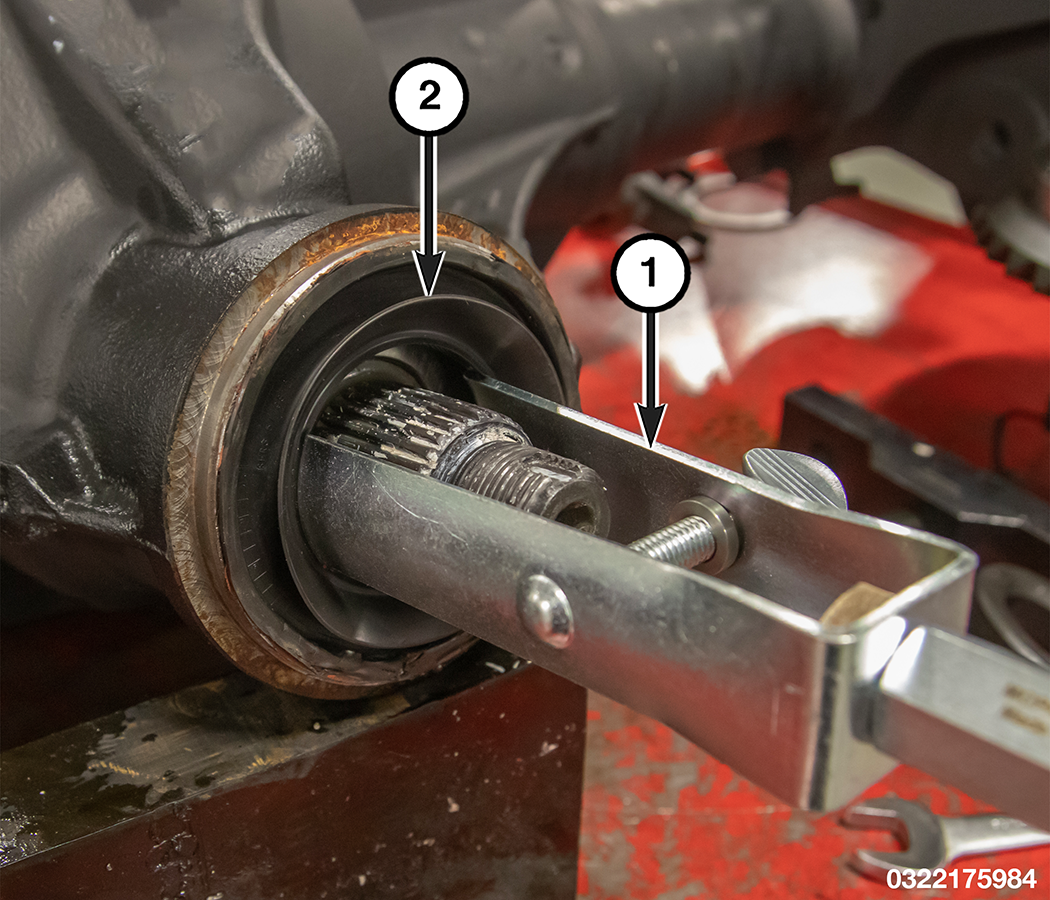
1 - Two Jaw Puller 2 - Pinion Flange - Remove and DISCARD the pinion seal from the differential case using Remover, Seal 7794-A and a slide hammer.
1 - Remover, Seal 7794-A 2 - Pinion Seal
INSTALLATION
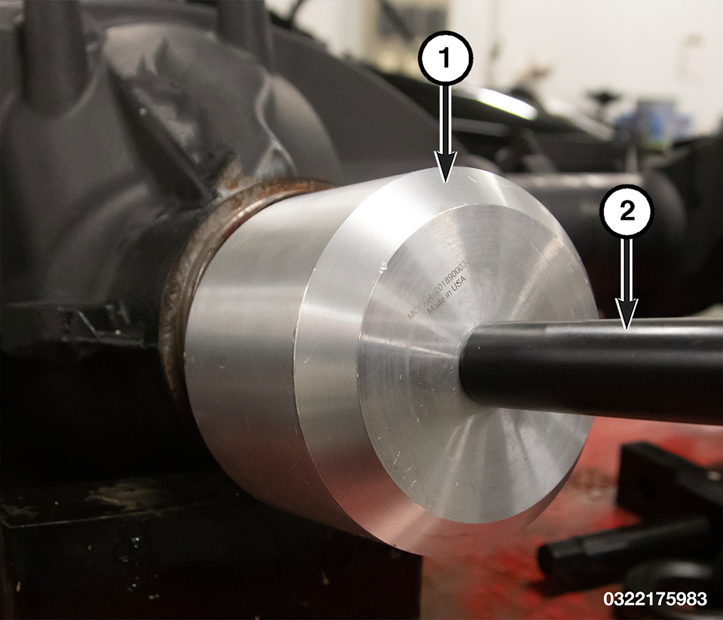
- Apply a light coating of gear lubricant on the lip of the pinion seal. Install the pinion seal using the Installer, Pinion Seal 2018900030 and Driver Handle, Universal C-4171 .
1 - Installer, Pinion Seal 2018900030 2 - Driver Handle, Universal C-4171 - Install the pinion flange on the pinion shaft with the reference marks aligned.
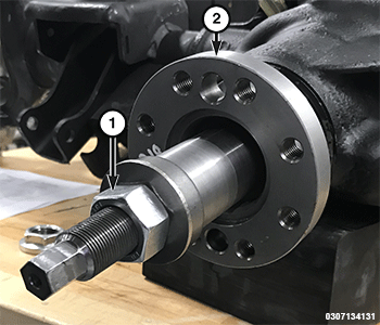
1 - Pinion Flange Installer 2076200030 2 - Pinion Flange - Install the pinion flange using the Pinion Flange Installer 2076200030 on the pinion shaft.
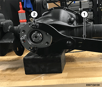
- Hold the pinion flange with Wrench, Spanner 6958 and tighten the NEW pinion nut to remove all end play.
1 - Wrench, Spanner 6958 2 - Bolts - Install a NEW nut on the pinion gear.
- Hold the pinion flange with Wrench, Spanner 6958 and tighten the pinion nut to the MINIMUM torque specification.
1 - Wrench, Spanner 6958 2 - Bolts - Measure the Pinion Torque To Rotate (PTTR) reading using an inch pound torque wrench. Pinion torque to rotate is the recorded reading plus 0.56 N·m (5 In. Lbs.).
1 - Inch Pound Torque Wrench - If PTTR is low, hold the pinion flange with a suitable tool and tighten the pinion nut in 6.8 N·m (5 Ft. Lbs.) increments until PTTR is achieved.
NOTE: If maximum tightening torque of 678 N·m (500 Ft. Lbs.) is reached before torque to rotate is achieved, the collapsible spacer may have been damaged. Never loosen pinion gear nut to decrease pinion gear bearing rotating torque and never exceed specified preload torque. Failure to follow these instruction may result in damage. - Install the driveshaft (Refer to 03 - Differential and Driveline/SHAFTS, Axle/Drive/Half/Removal and Installation) .
- Install the brake rotors (Refer to 05 - Brakes, Base/Hydraulic/Mechanical/ROTOR, Brake/Removal and Installation) .
 TORQUE SPECIFICATIONS - M250 DIFFERENTIAL