Removal and Installation
Differential Assembly - C235 - Open
▸Contents: 03 - Differential and Driveline
Description and Operation
Diagnosis and Testing
ASSEMBLY, Differential
Disassembly and Assembly
Actuator/Motor
GEAR, Ring and Pinion
Removal and Installation
Joints
SHAFTS, Axle/Drive/Half
Valves
Removal and Installation
REMOVAL
- Raise and support the vehicle (Refer to 04 - Vehicle Quick Reference/Hoisting/Standard Procedure) .
- Remove the fill and drain plugs from the differential housing.
- Remove the differential cover (Refer to 03 - Differential and Driveline/COVER/Removal and Installation) .
- Clean the housing cavity with brake cleaner and a lint free cloth.
NOTE: Do not use steam, kerosene or gasoline to clean the housing.
- Remove the axle shafts (Refer to 03 - Differential and Driveline/SHAFTS, Axle/Drive/Half/Removal and Installation) .
NOTE: Side play resulting from bearing races being loose on case hubs requires replacement of the differential case.
- Mark the differential housing and bearing caps for installation reference.
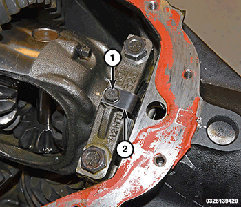
- Remove the adjuster lock bolt and remove the adjuster lock tab.
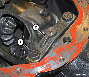
1 – Adjuster Lock Bolt 2 – Adjuster Lock Tab - Loosen the differential bearing cap bolts.
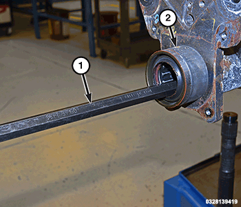
1 – Differential Bearing Cap Bolts 2 – Differential Bearing Cap - Loosen the differential bearing adjusters through the axle tubes using Wrench, Differential Preload C-4164 .
1 – Wrench, Differential Preload C-4164 2 – Axle Tube - Hold the differential case while removing the bearing caps.
NOTE: Tag the differential bearing cups and the threaded adjusters after removal to indicate their location.
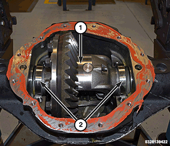
1 – Differential Case 2 – Bearing Cups - Remove the differential case and bearing cups.
INSTALLATION
- Apply a coating of hypoid gear lubricant to the differential bearings and bearing cups.
- Install the differential case with the bearing cups into the housing.
1 – Differential Case 2 – Bearing Cups - Install the differential bearing caps with the bearing cap bolts in their original locations.
1 – Differential Bearing Cap Bolts 2 – Differential Bearing Cap - Tighten the upper bolts to 14 N⋅m (10 ft. lbs.). Tighten the lower bolts finger-tight until the bolt head is seated. Perform the differential bearing preload and adjustment procedure (Refer to 03 - Differential and Driveline/Adjustments) .
NOTE: Verify that all of the bearing cap bolts are tightened to the proper (Torque Specifications) before proceeding.
- Install the axle shafts (Refer to 03 - Differential and Driveline/SHAFTS, Axle/Drive/Half/Removal and Installation) .
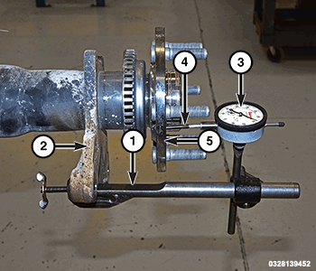
- Mount the dial indicator post on the axle tube flange.
1 – Dial Indicator Post 2 – Axle Tube Flange 3 – Dial Indicator 4 – Dial Indicator Plunger 5 – Axle Shaft - Push the axle shaft inward until the end touches the differential pinion mate shaft. Set the dial indicator plunger on the end of axle shaft flange surface and zero the dial indicator.
NOTE: The end-play specification should be 0.13 mm - 0.38 mm (0.005 - 0.015 in.). If the specification can not be met, it may be necessary to re-shim the side gears or replace the differential case.
- Pull the axle shaft out until it stops and record the dial indicator end-play reading. Rotate the axle shaft about 180 degrees and record the dial indicator end-play reading again. The two readings should be within 0.05 mm (0.002 in.).
- Conduct the same procedure on the axle shaft on the opposite side.
- Install a NEW pinion mate shaft lock screw.
- Install the differential cover (Refer to 03 - Differential and Driveline/COVER/Removal and Installation) .
- Fill the differential with lubricant to the proper specification (Refer to 04 - Vehicle Quick Reference/Capacities and Recommended Fluids - Specifications) .
- Remove the support and lower the vehicle.
 TORQUE SPECIFICATIONS - C235 DIFFERENTIAL