Removal and Installation
215fd - 3.0l Diesel
▸Contents: 03 - Differential and Driveline
Description and Operation
Diagnosis and Testing
ASSEMBLY, Differential
Disassembly and Assembly
Actuator/Motor
GEAR, Ring and Pinion
Removal and Installation
Joints
SHAFTS, Axle/Drive/Half
Valves
Removal and Installation
REMOVAL
- Disconnect and isolate the negative battery cable(s) (Refer to 08 - Electrical/Battery System/Standard Procedure) .
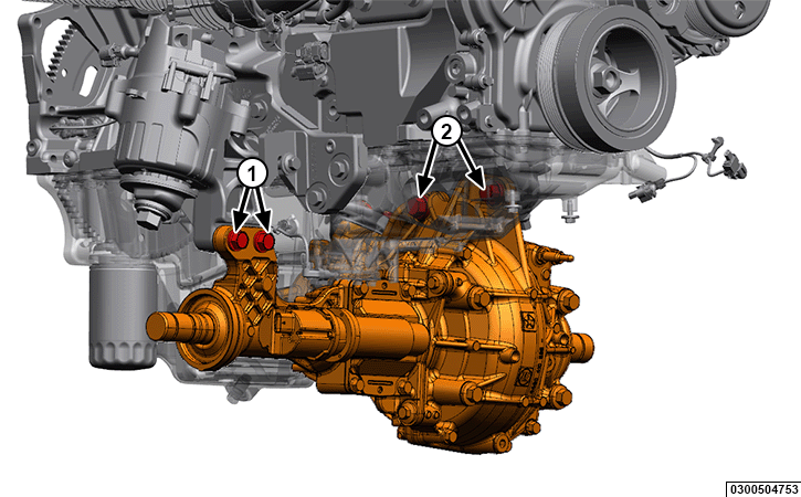
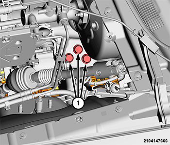
- Remove the three fasteners from pinion mounting bracket.
1 - Fasteners - Raise and support the vehicle (Refer to 04 - Vehicle Quick Reference/Hoisting/Standard Procedure) .
- Remove the skid plate if equipped (Refer to 13 - Frame and Bumpers/Under Body Protection/PLATE, Skid, Front/Removal and Installation) .
- Remove the half shafts (Refer to 03 - Differential and Driveline/SHAFTS, Axle/Drive/Half/Removal and Installation) .
- Remove the front driveshaft (Refer to 03 - Differential and Driveline/SHAFTS, Axle/Drive/Half/Removal and Installation) .
- Remove the crossmember (Refer to 13 - Frame and Bumpers/Frame/CROSSMEMBER, Front Suspension/Removal and Installation) .
- Remove the steering gear (Refer to 19 - Steering/GEAR/Removal and Installation) .
CAUTION: Remove axle vent tube prior to removing axle. Failure to remove vent tube will allow axle fluid to saturate the vent and cause reduced or improper axle venting resulting in axle damage.
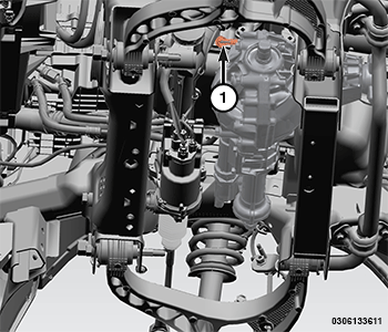
- Remove the front axle vent tube.
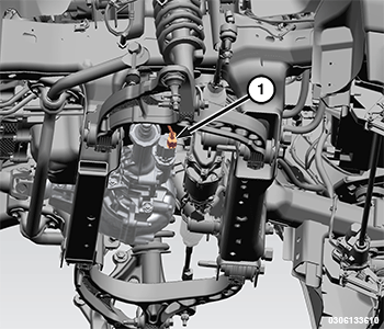
1 - Front Axle Vent Tube - Disconnect the Front Axle Disconnect (FAD) actuator wire harness connector.
1 - Wire Harness Connector - Support the rear of engine with a safety stand or jack.
- Support the front axle with a suitable jack.
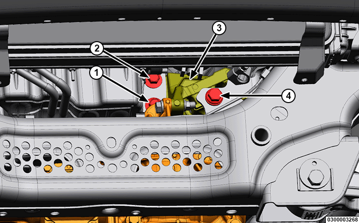
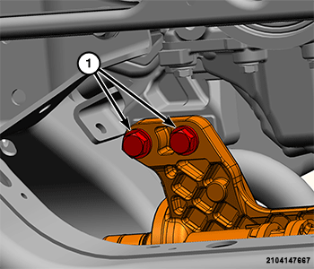
- Remove the three isolator mounting bolts.
1 - Mounting Bolts - Remove the front axle output shaft tube mounting bolts and the wire harness bracket.
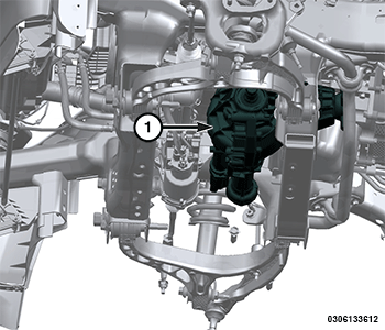
1 - Mounting Bolts - Lower the front axle from the vehicle with the isolator mount still attached to the front axle.
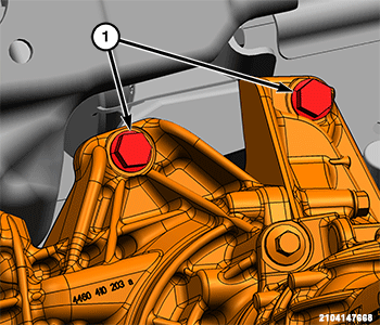
1 - Front Axle - Remove the front axle mounting bolts and remove the isolator from the front axle.
1 - Mounting Bolts
INSTALLATION
Follow the removal procedure in reverse for general reassembly of the components on the vehicle. The steps listed below are calling out specific procedures that should be followed during installation.
- Install a NEW front axle vent tube.
- Verify the differential fluid level and add fluid if necessary (Refer to 04 - Vehicle Quick Reference/Capacities and Recommended Fluids/Specifications) .
- Lower the vehicle to access the pinion mounting bracket.
-
CAUTION: Failure to properly torque axle mounting bolts may result in axle damage.
| NOTE: | The vent cap must point upward. The position of the vent cap must be between the 10 o'clock and 11 o'clock position with the cap aligning with the engine isolator/axle housing bolted joint when looking at the axle from the front of vehicle. |
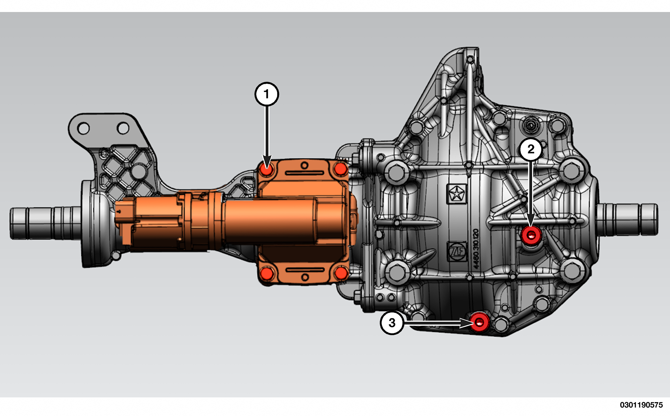
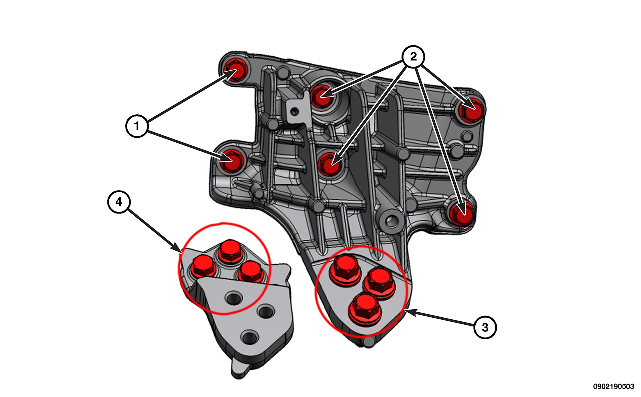
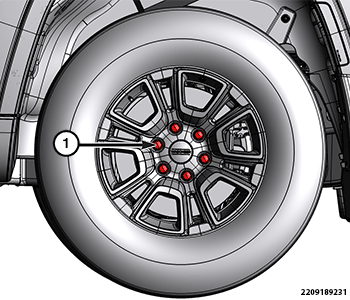
 TORQUE SPECIFICATIONS - 215FD FRONT AXLE