Removal and Installation
Output Shaft - 215fd
▸Contents: 03 - Differential and Driveline
Description and Operation
Diagnosis and Testing
ASSEMBLY, Differential
Disassembly and Assembly
Actuator/Motor
GEAR, Ring and Pinion
Removal and Installation
Joints
SHAFTS, Axle/Drive/Half
Valves
Removal and Installation
REMOVAL
- Raise and support the vehicle (Refer to 04 - Vehicle Quick Reference/Hoisting/Standard Procedure) .
- Remove the halfshaft from the disconnect side of the axle (Refer to 03 - Differential and Driveline/SHAFTS, Axle/Drive/Half/Removal and Installation) .
- Remove and DISCARD the snap ring and O-ring from the output shaft.
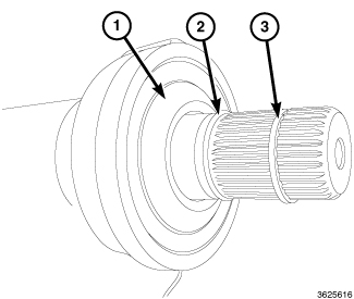
1 - Oil Slinger 2 - O-Ring 3 - Snap Ring - Remove and DISCARD the oil slinger.
- Remove and DISCARD the axle seal from the axle tube.
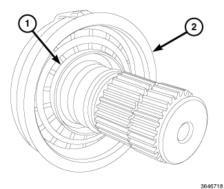
1 - Axle Seal 2 - Axle Tube - Disconnect the Front Axle Disconnect (FAD) wire harness connector.
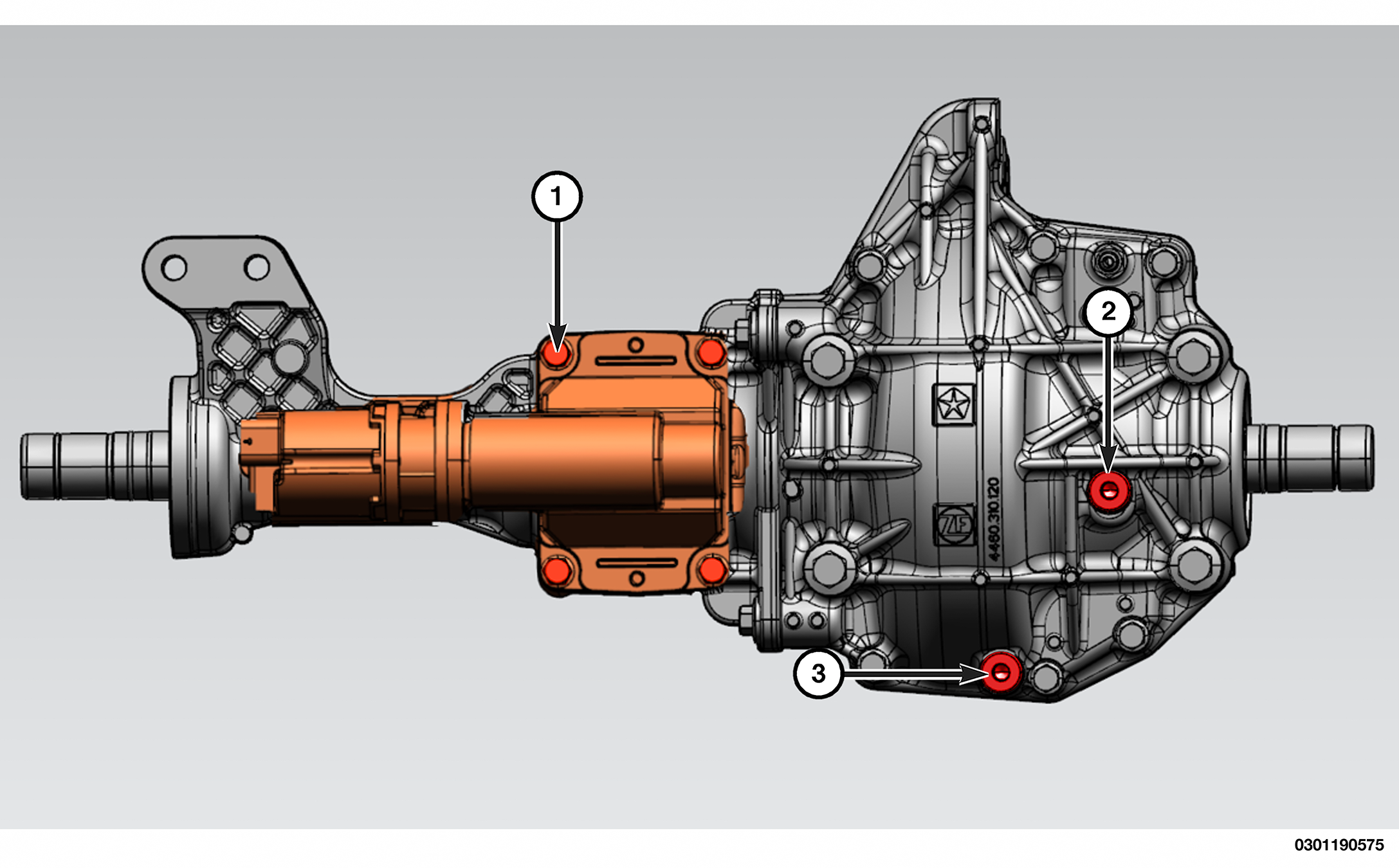
1 - Front Axle Disconnect (FAD) Actuator Bolts 2 - Fill Plug 3 - Drain Plug - Remove the (FAD) actuator bolts.
- Remove the FAD from the housing.
- Remove the axle tube assembly bolts.
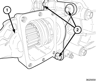
1 - Axle Tube Assembly 2 - Axle Tube Assembly Bolts - Remove the axle tube assembly.
- Remove the output shaft snap ring from the axle tube.
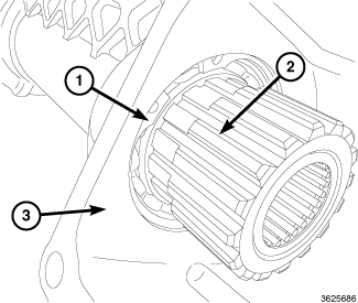
1 - Output Shaft Snap Ring 2 - Output Shaft 3 - Axle Tube - Remove the output shaft from the axle tube.
INSTALLATION
|
|
|
| 1 - Output Shaft Snap Ring |
| 2 - Output Shaft |
| 3 - Axle Tube |
- Install the output shaft in the axle tube.
- Install the output shaft snap ring in the axle tube.
- Install the FAD collar on the output shaft.
- Apply a 1.5 mm (0.06 in.) bead of Mopar™ Silicone Rubber Sealant or equivalent to axle tube mounting surface.
CAUTION: If axle tube is not installed within 3 to 5 minutes, the tube must be cleaned and new RTV applied. Failure to follow these instructions will result in a leak.
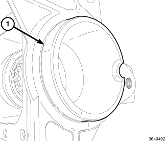
1 - Axle Tube Mounting Surface - Apply a 1.5 mm (0.06 in.) bead of Mopar™ Silicone Rubber Sealant or equivalent to the axle housing mounting surface.
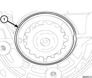
1 - Axle Tube Mounting Surface - Install the axle tube assembly with the axle tube bolts and tighten to the proper torque specifications.
1 - Axle Tube Assembly 2 - Axle Tube Assembly Bolts - Clean the FAD sealing surface and install a NEW gasket.
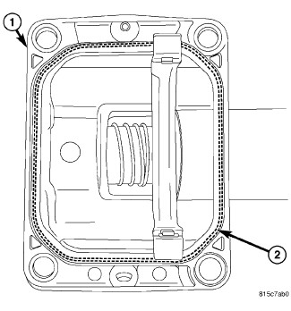
1 - FAD Sealing Surface 2 - FAD Gasket - Align the FAD shift fork with the disconnect collar and install the FAD to the housing disconnect pocket.
NOTE: The FAD bolts must be tightened in a clockwise pattern, starting at the top left corner (11 o’clock position). 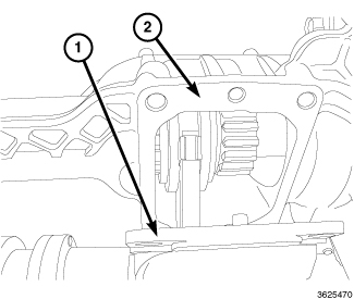
1 - FAD 2 - Disconnect Pocket - Install the FAD bolts and tighten to the proper torque specifications.
1 - Front Axle Disconnect (FAD) Actuator Bolts 2 - Fill Plug 3 - Drain Plug - Connect the FAD wire harness connector.
- Wipe the axle shaft tube bore clean.
- Install a NEW axle shaft seal using Installer, Seal 10399 and Driver Handle, Universal C-4171 .
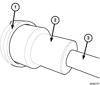
1 - Axle Shaft Seal 2 - Installer, Seal 10399 3 - Driver Handle, Universal C-4171 - Install a NEW oil slinger using Installer, Bearing L-4507 ..
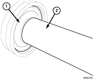
1 - Oil Slinger 2 - Installer, Bearing L-4507 - Install a NEW O-ring and snap ring on the axle shaft.
1 - Oil Slinger 2 - O-Ring 3 - Snap Ring - Install the halfshaft (Refer to 03 - Differential and Driveline/SHAFTS, Axle/Drive/Half/Removal and Installation) .
- Verify the differential fluid level and add fluid if necessary (Refer to 04 - Vehicle Quick Reference/Capacities and Recommended Fluids/Specifications) .
- Remove the support and lower the vehicle.
 TORQUE SPECIFICATIONS - 215FD FRONT AXLE